I1010
10 × 10 mm
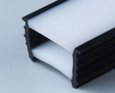
Edgeless silicone cover
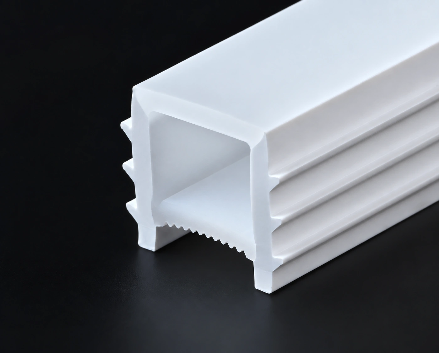
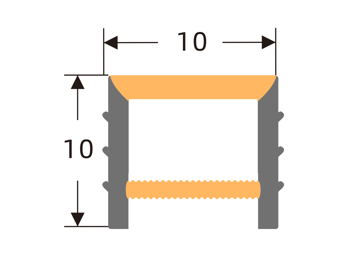
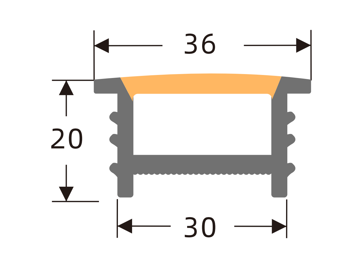
Compare 101 edgeless, white-edge, H-type flanged, black-face and white-face silicone covers with black edges. View photos and profile drawings; select by size and PCB width. LED strips are not included.
Silicone covers only · LED strips not included
APPLICATIONS
Explore interior lighting ideas, understand the component assembly, and compare dimensions in one place.
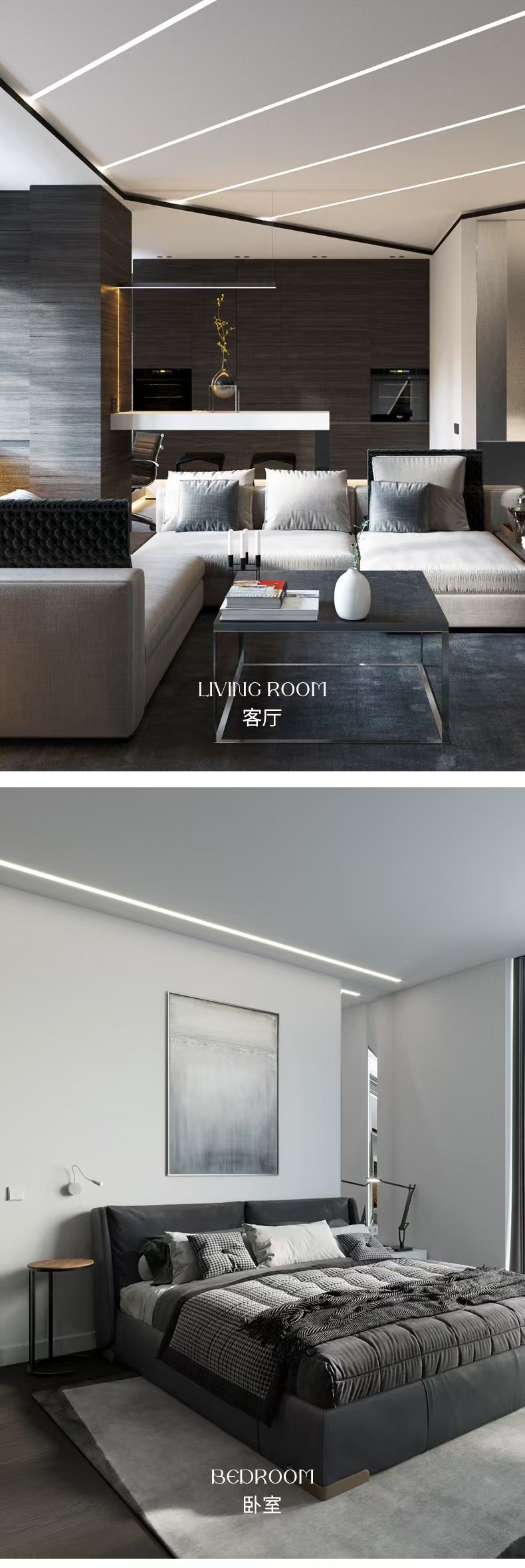
Ceiling and wall lines trace the room’s architecture.
Simple lighting lines complement furniture and ceiling layouts.
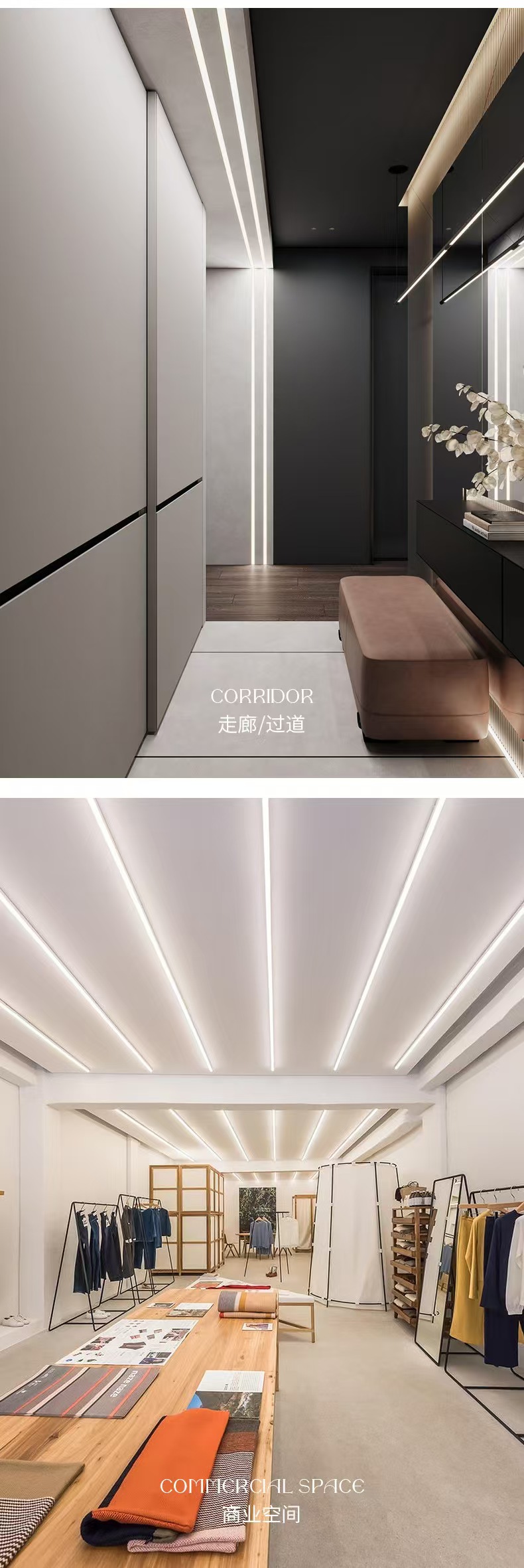
Continuous ceiling or wall lines connect spaces visually.
Parallel and angled lines complement shop and display layouts.
Application images illustrate lighting concepts, not specific catalogue models. LED strips, channels / bases and power supplies are selected separately. Colour and brightness depend on the light source and complete assembly.
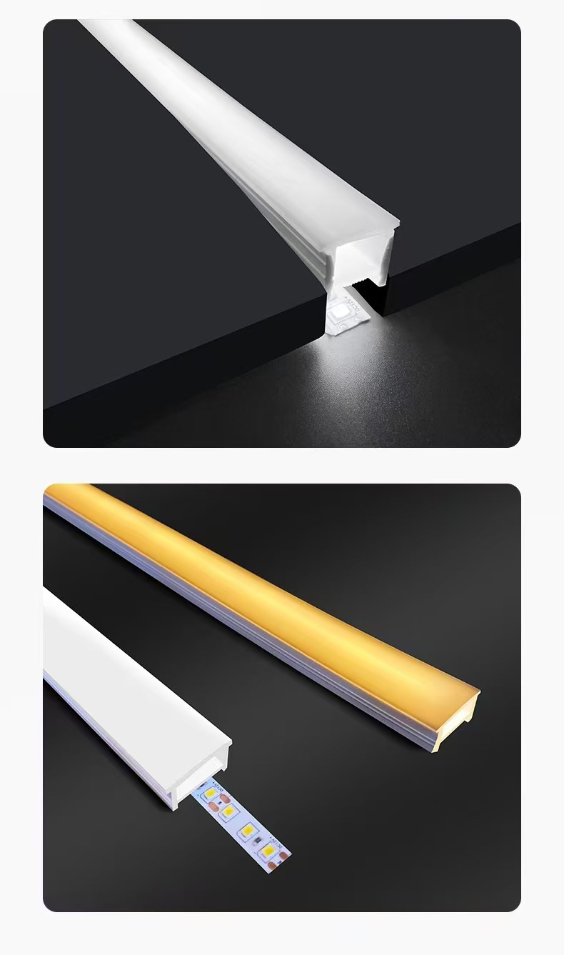
ASSEMBLY DETAILS
The product supplied on this page. Choose the appearance, then check cross-section dimensions and fit.
Not included with the cover. Colour temperature, brightness and electrical specifications depend on the selected strip and power supply.
Selected separately. Confirm the slot, edges and fixing method against the model drawing and a physical sample.
INSTALLATION
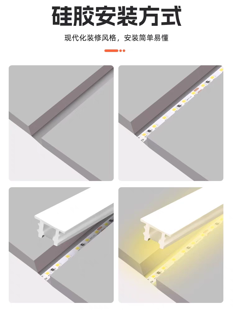
The diagram shows the basic sequence for a recessed installation. Confirm slot width, depth and fixing method against the selected model drawing and a physical sample.
Confirm slot width and depth from the silicone-cover cross-section and physical sample before machining the recess.
With power isolated, place and secure the compatible LED strip in the recess.
After wiring, energise briefly to test; isolate power again before continuing.
Press the silicone cover evenly into the recess. Avoid twisting, hard pulling or sharp tools.
Electrical wiring must be completed by suitably qualified personnel following the strip and power-supply instructions. The LED strip, power supply and recessed substrate are not included with the silicone cover.
All 101 model photographs and PDF dimension drawings remain below. Application references do not replace drawings or establish compatibility with a specific model.
101 · Enlarge image · mm
Showing 101 of 101 models
I1010
I1212
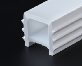
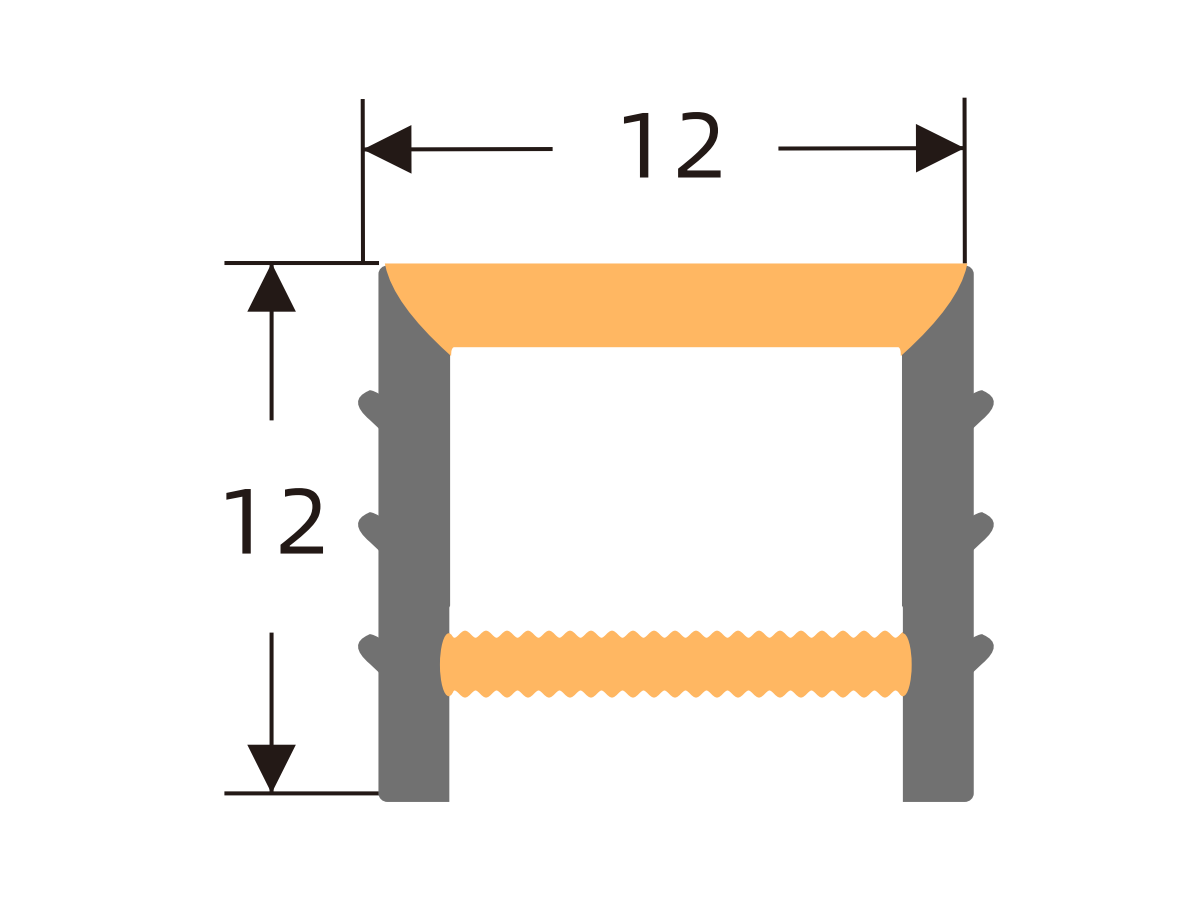
I1414
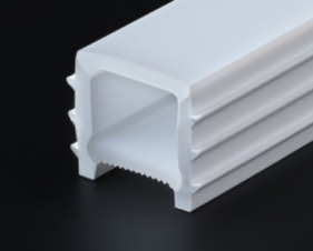
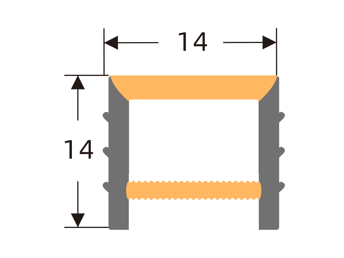
I1510
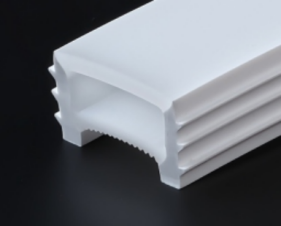
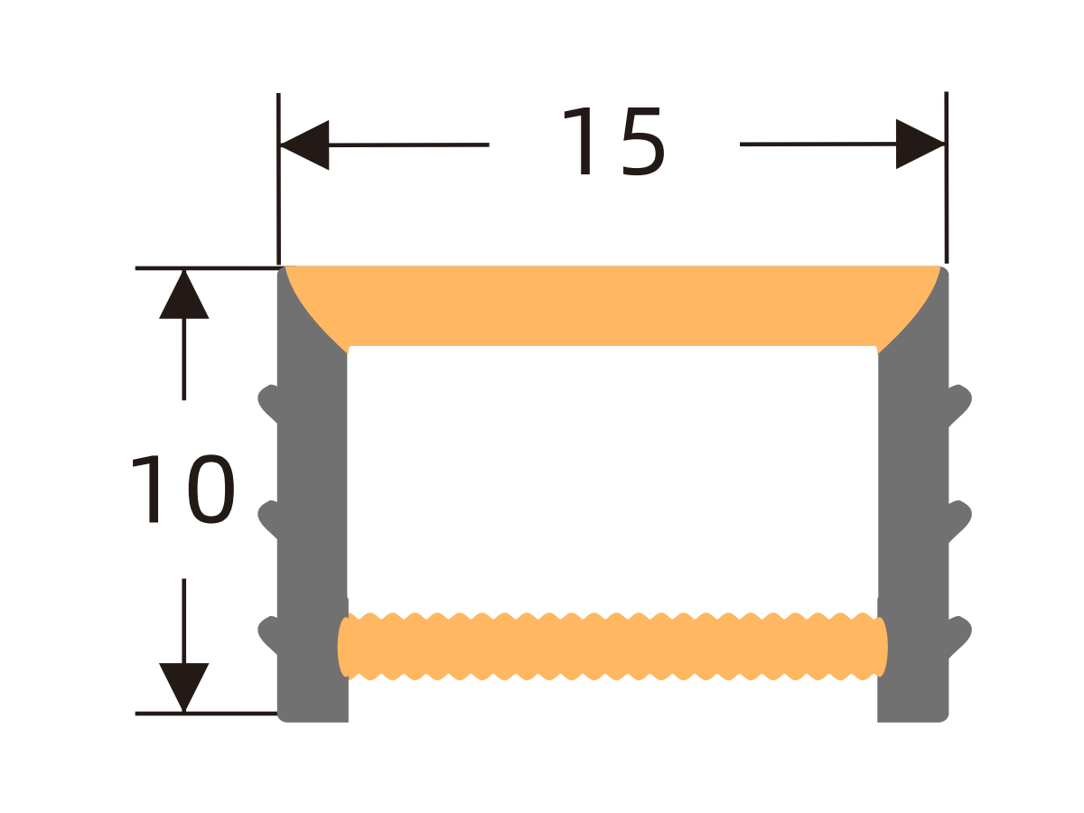
I1515
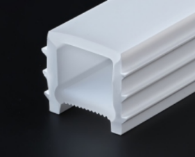
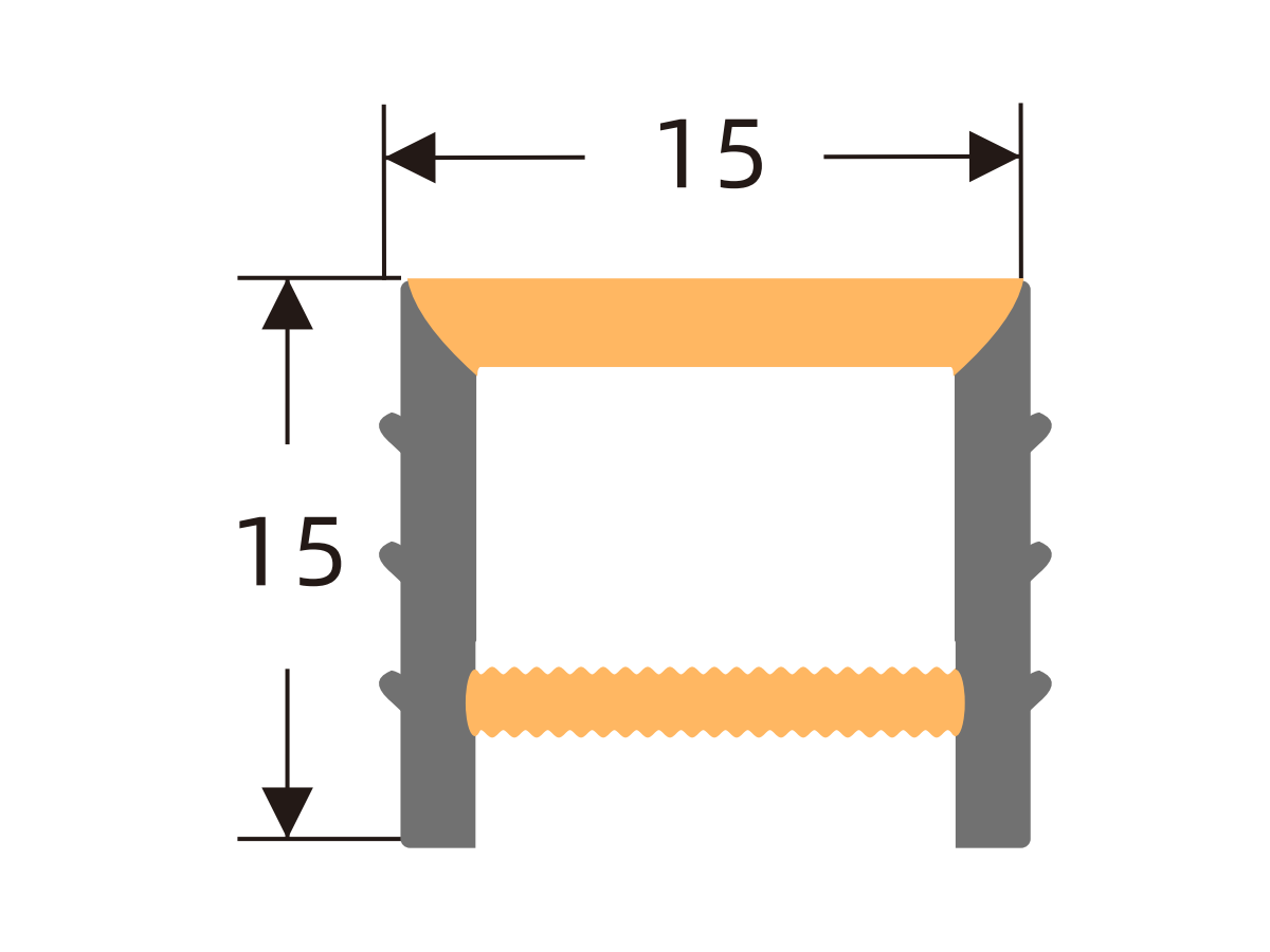
I1610
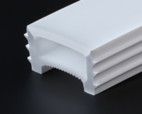
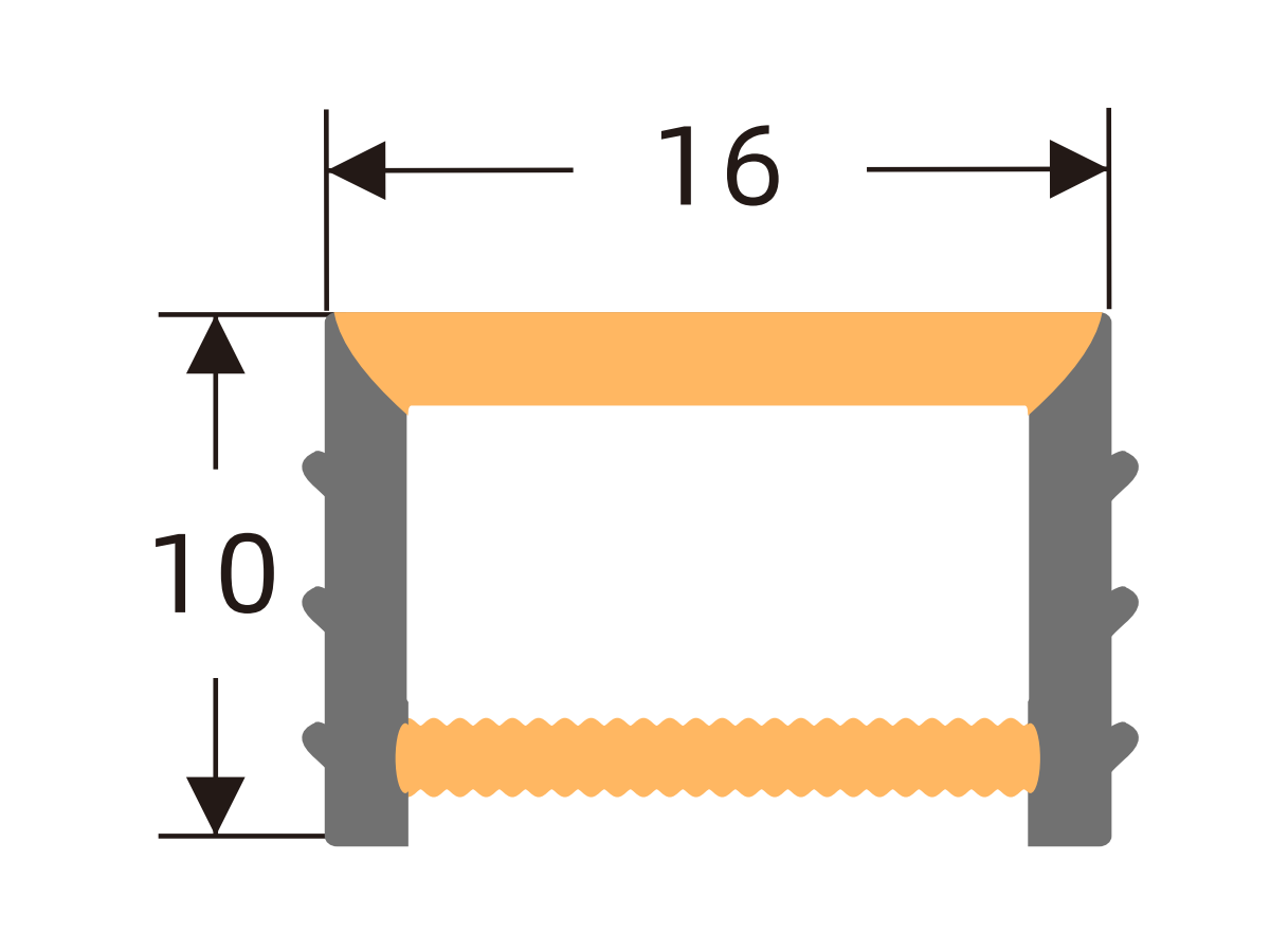
I1616
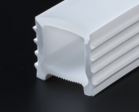
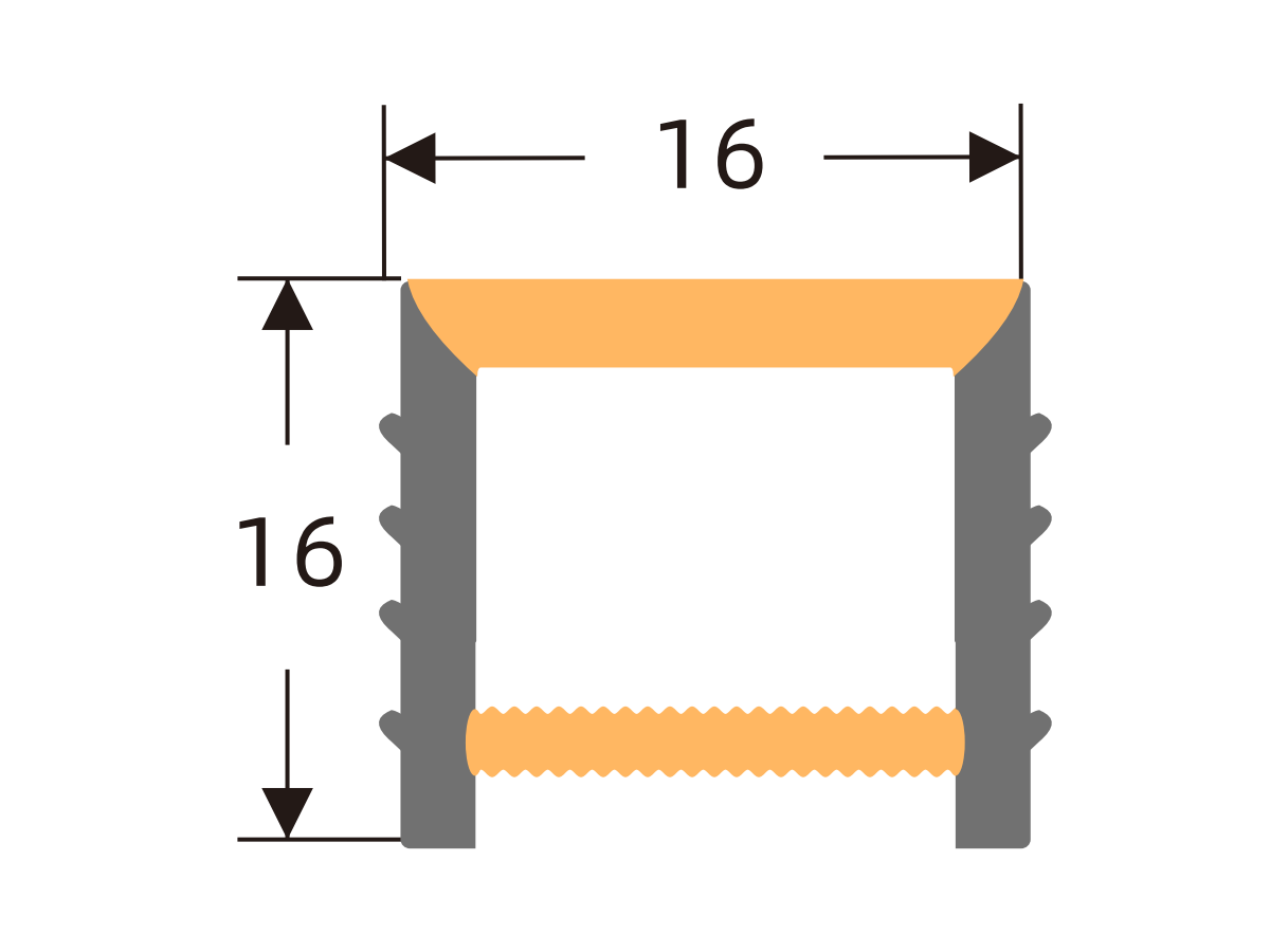
I2010
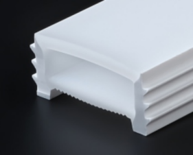
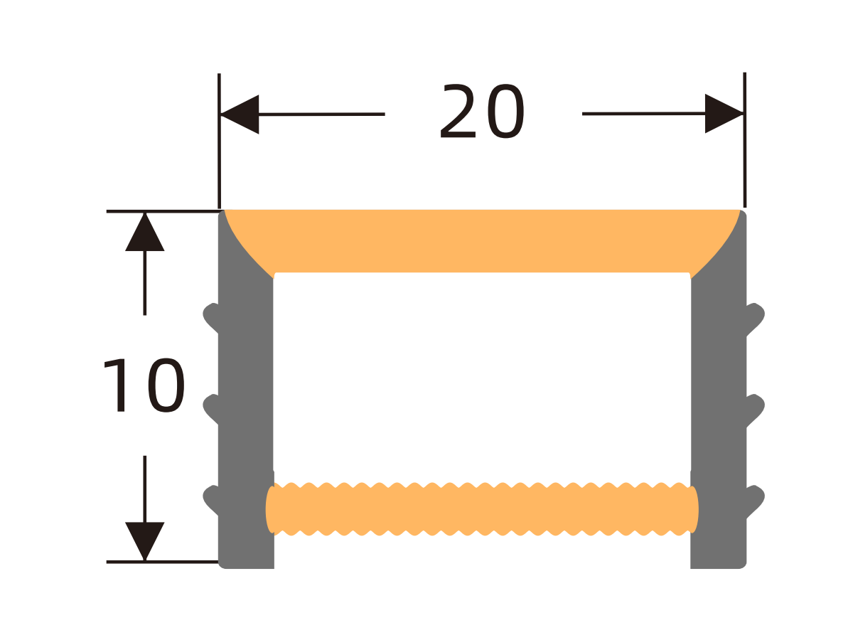
I2014
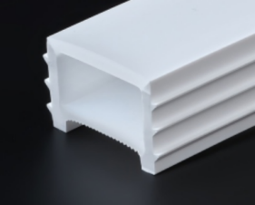
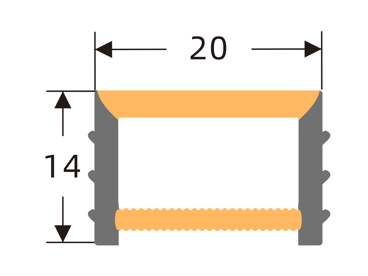
I2020
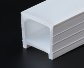
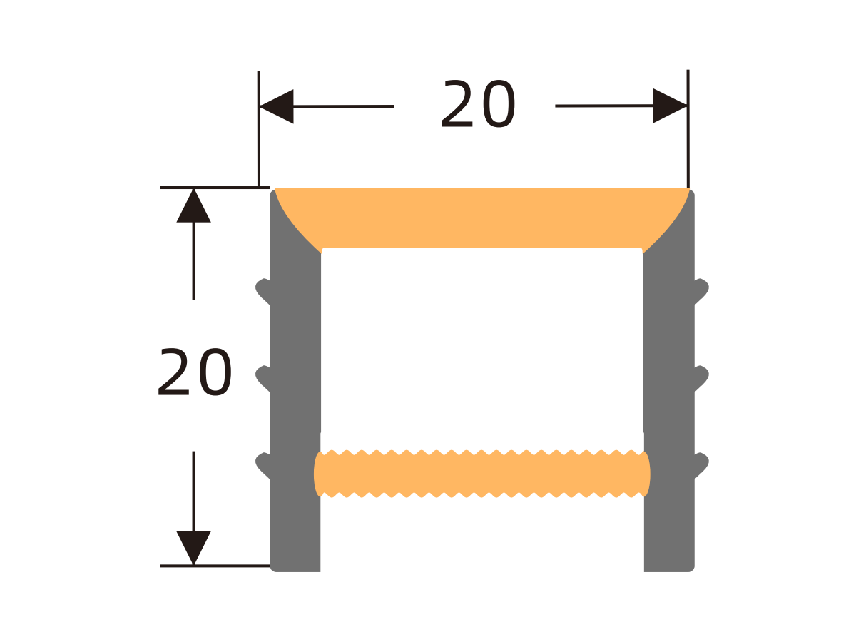
I2520
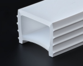
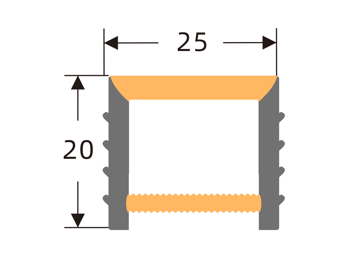
I3010
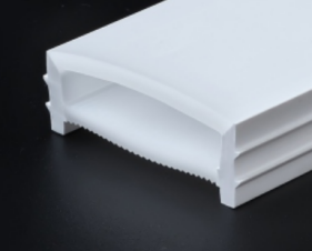
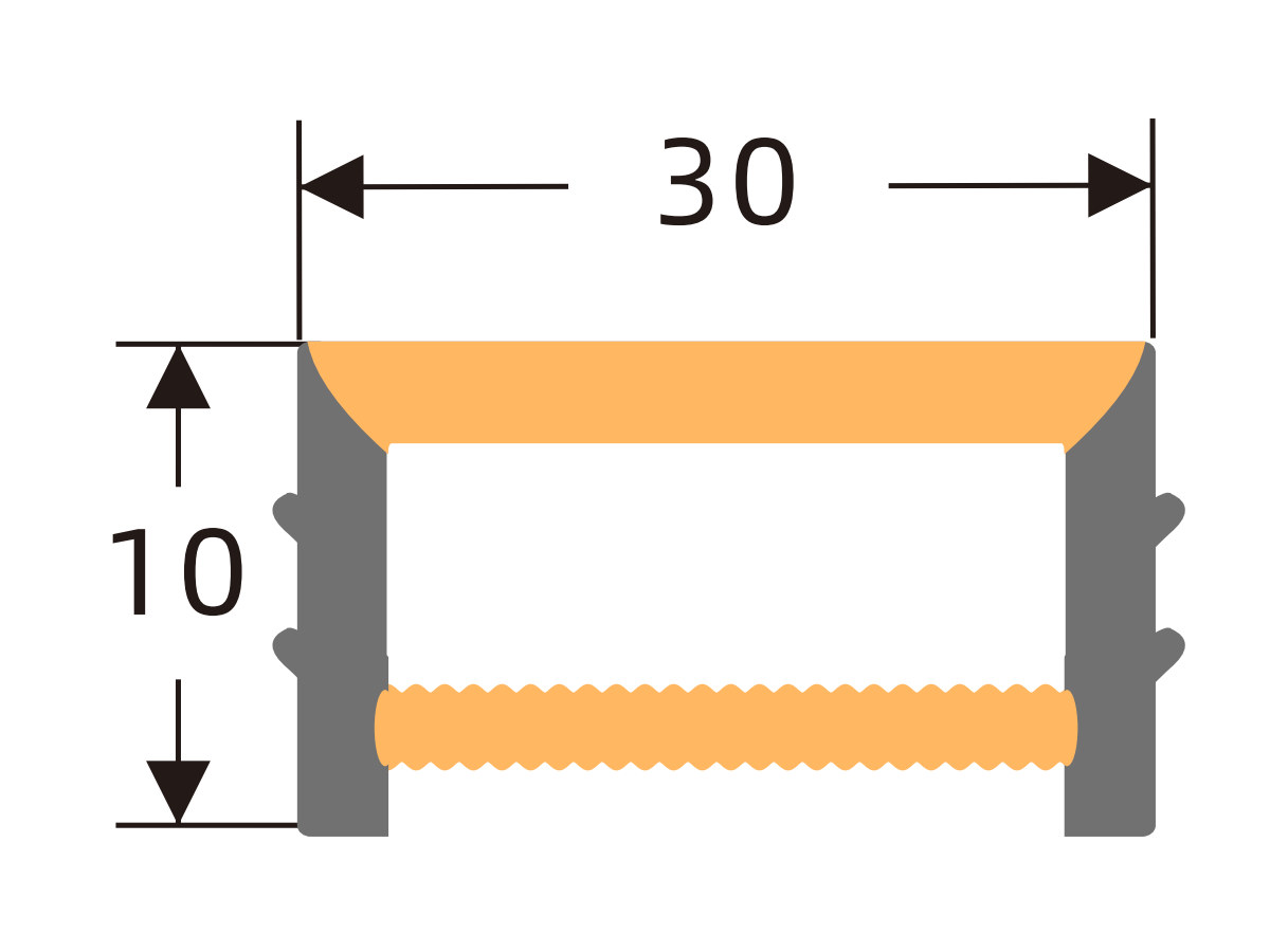
I3020
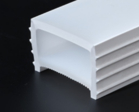
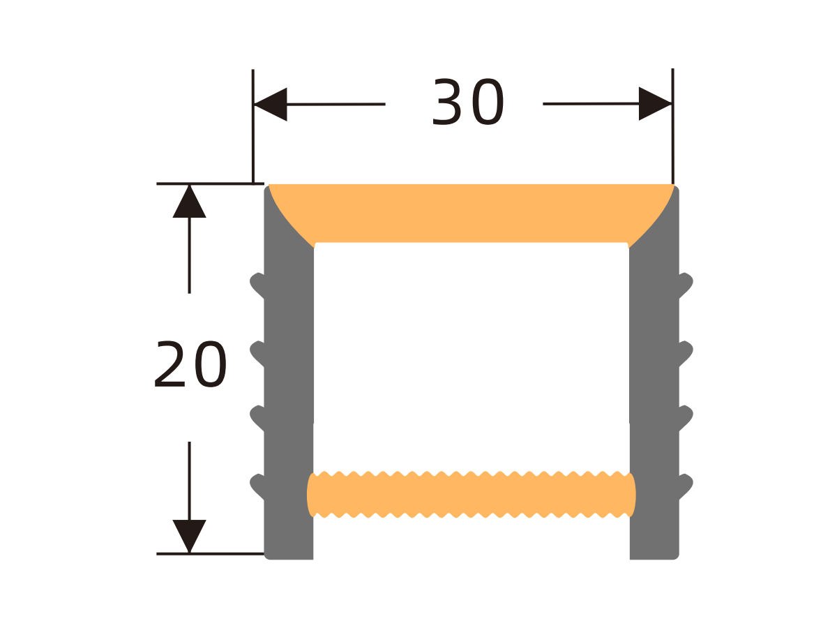
I4020
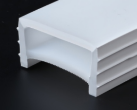
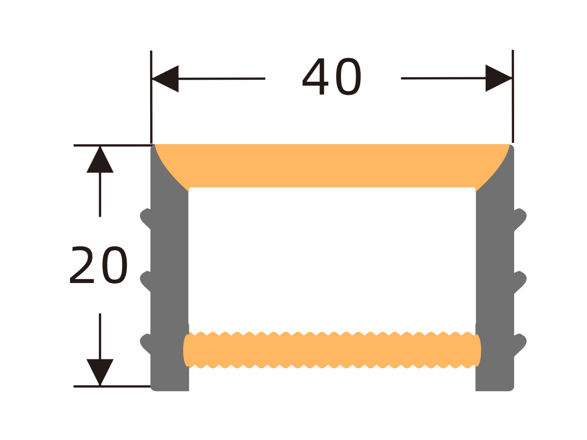
I4025
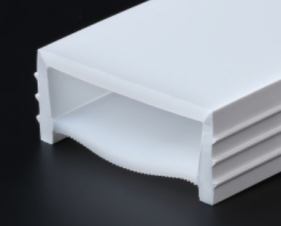
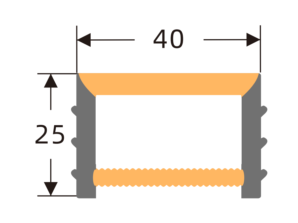
I5020
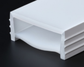
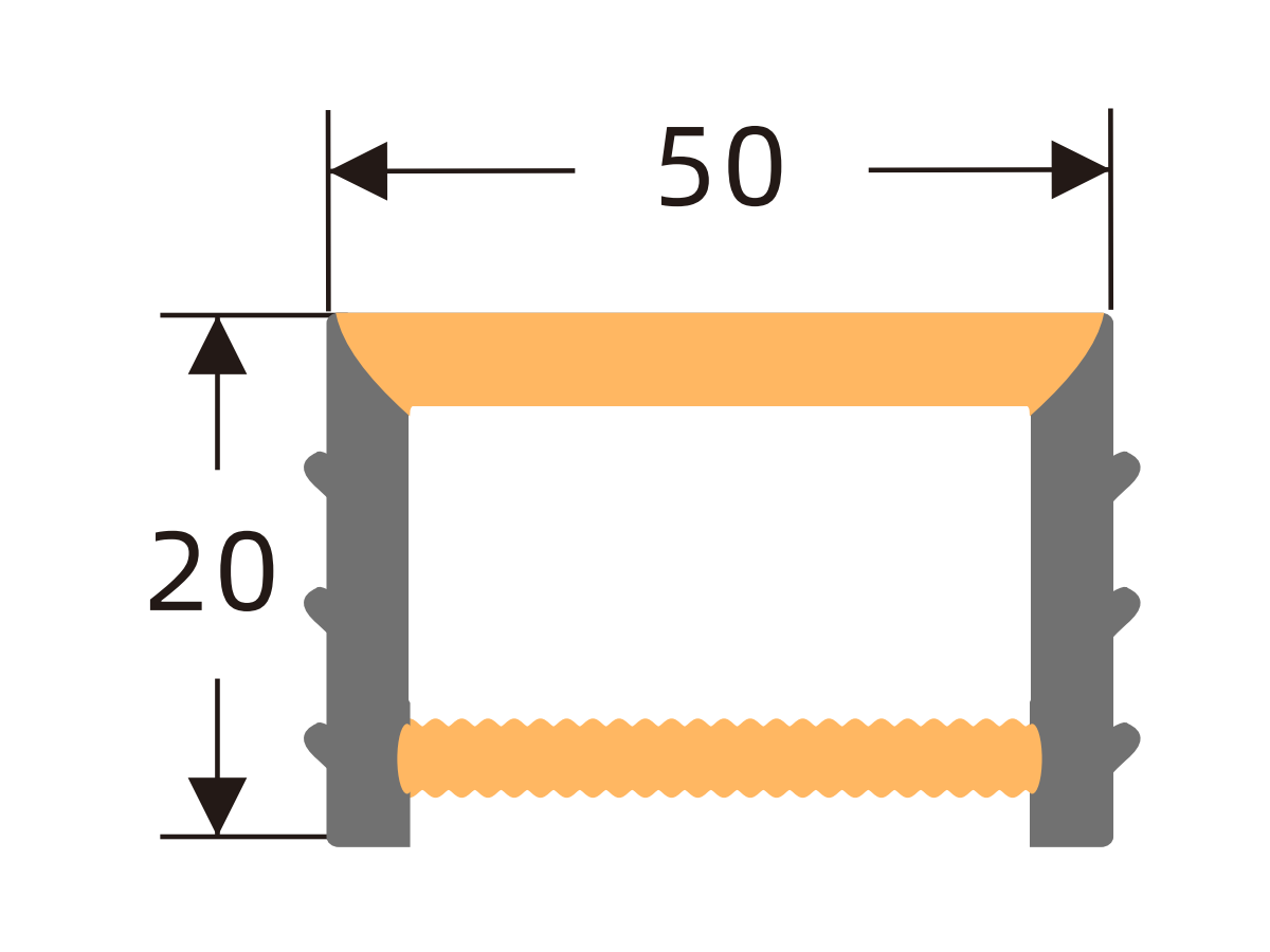
J0606 A
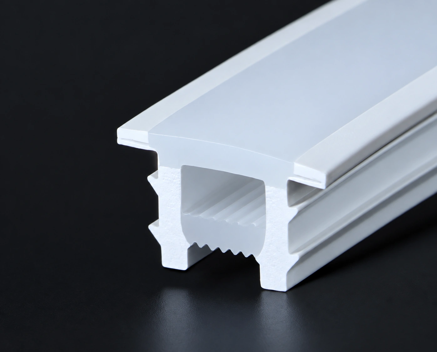
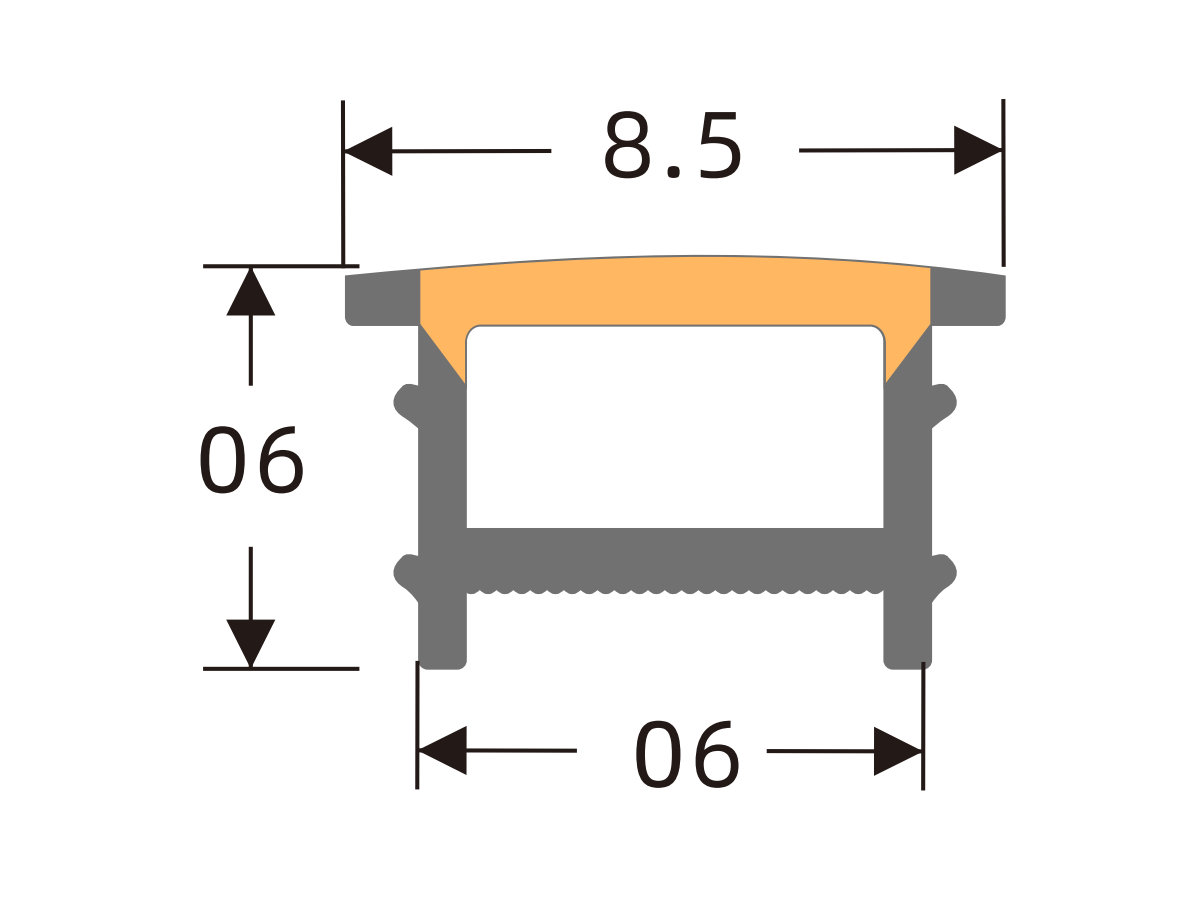
J0808 A
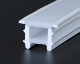
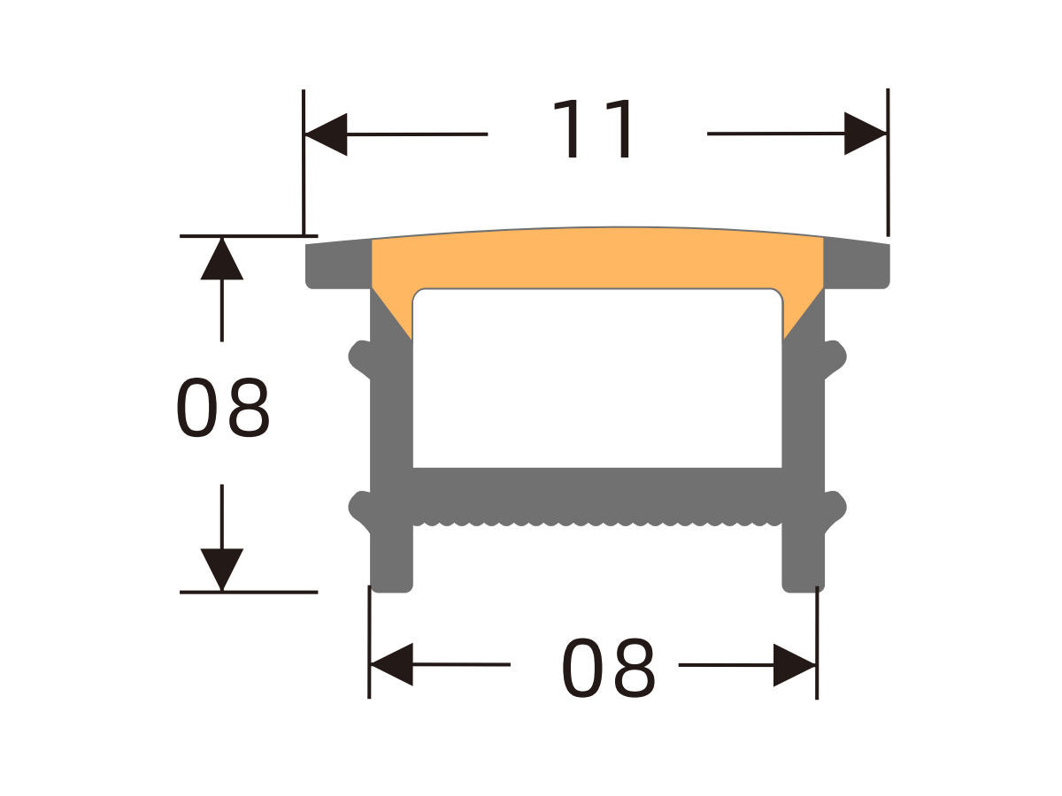
J1010 A
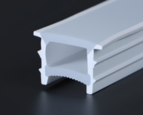
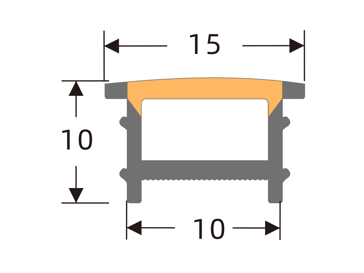
J1210 A
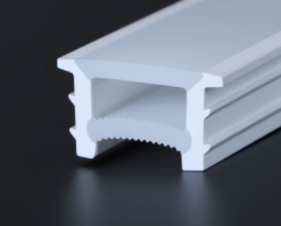
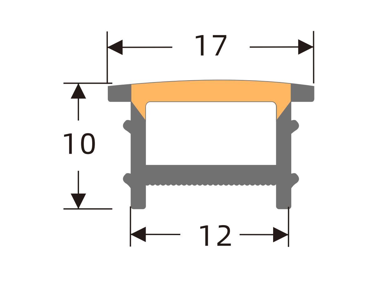
J1212 A
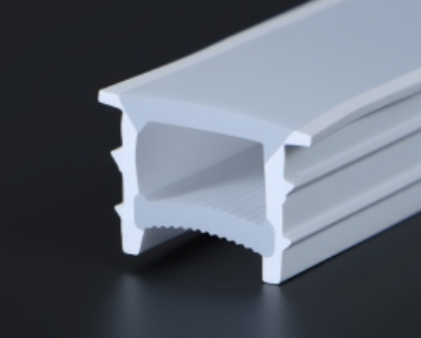
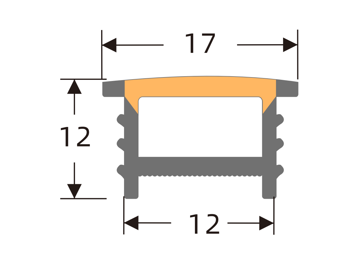
J1410 A
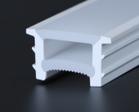
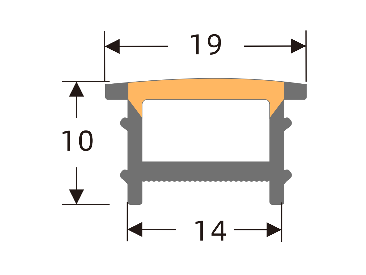
J1414 A
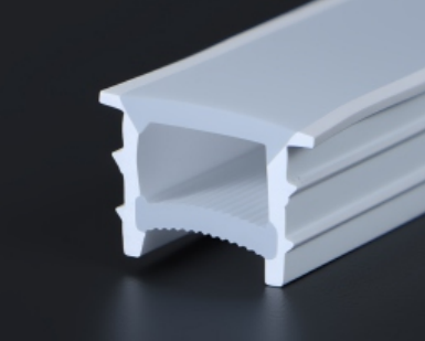
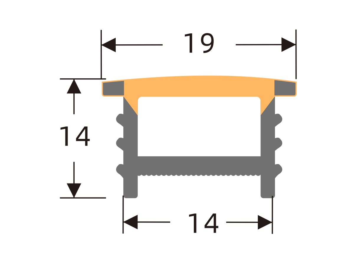
J1510 A
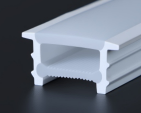
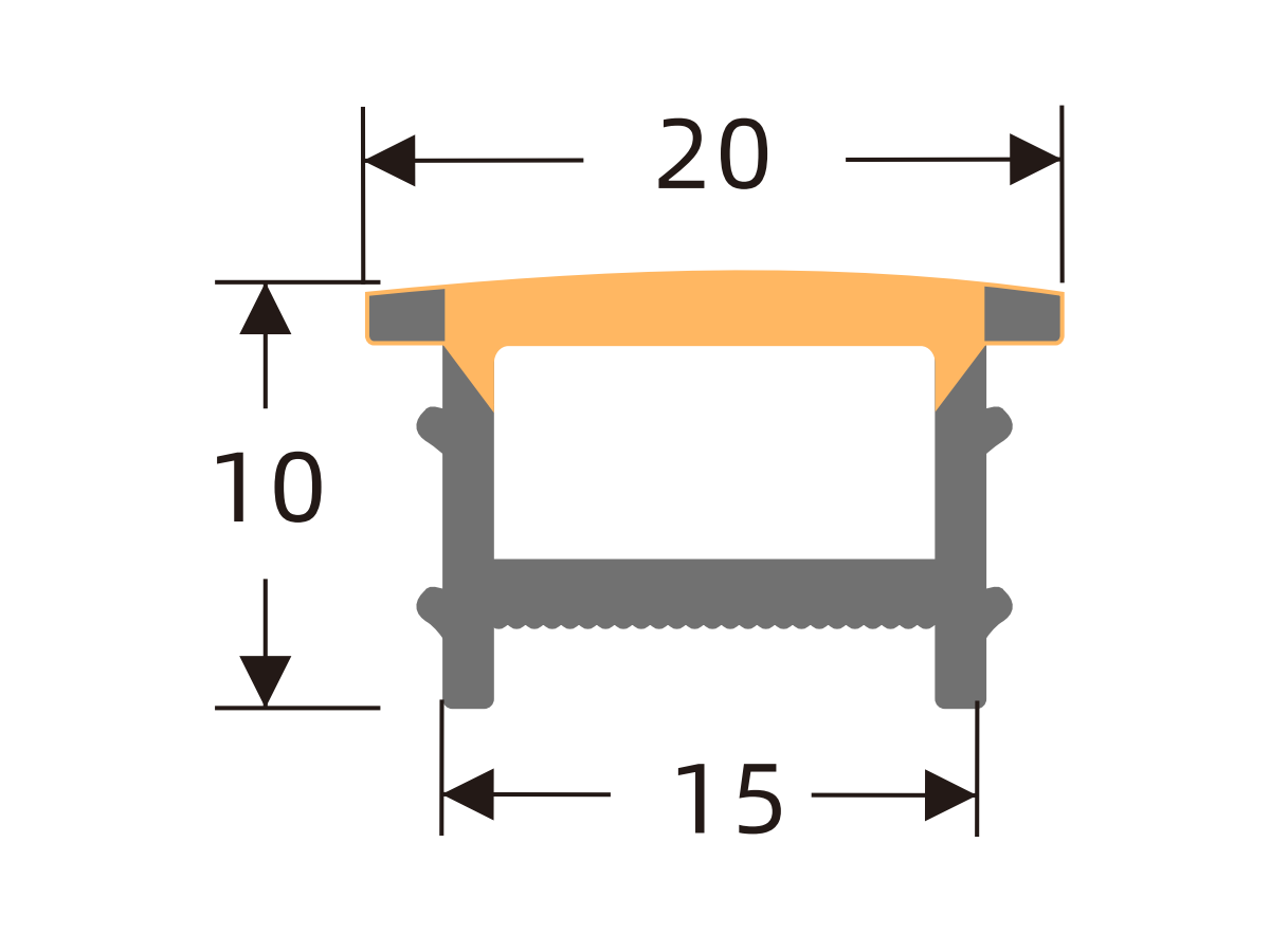
J1515 A
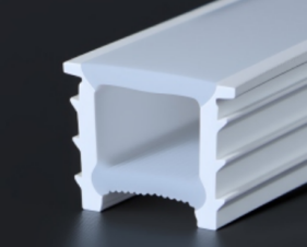
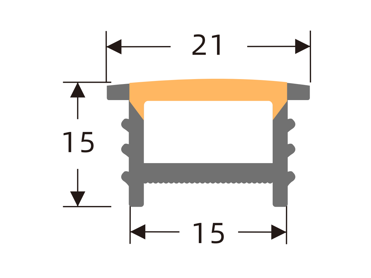
J1610 A
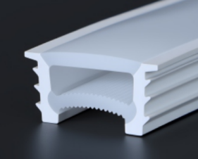
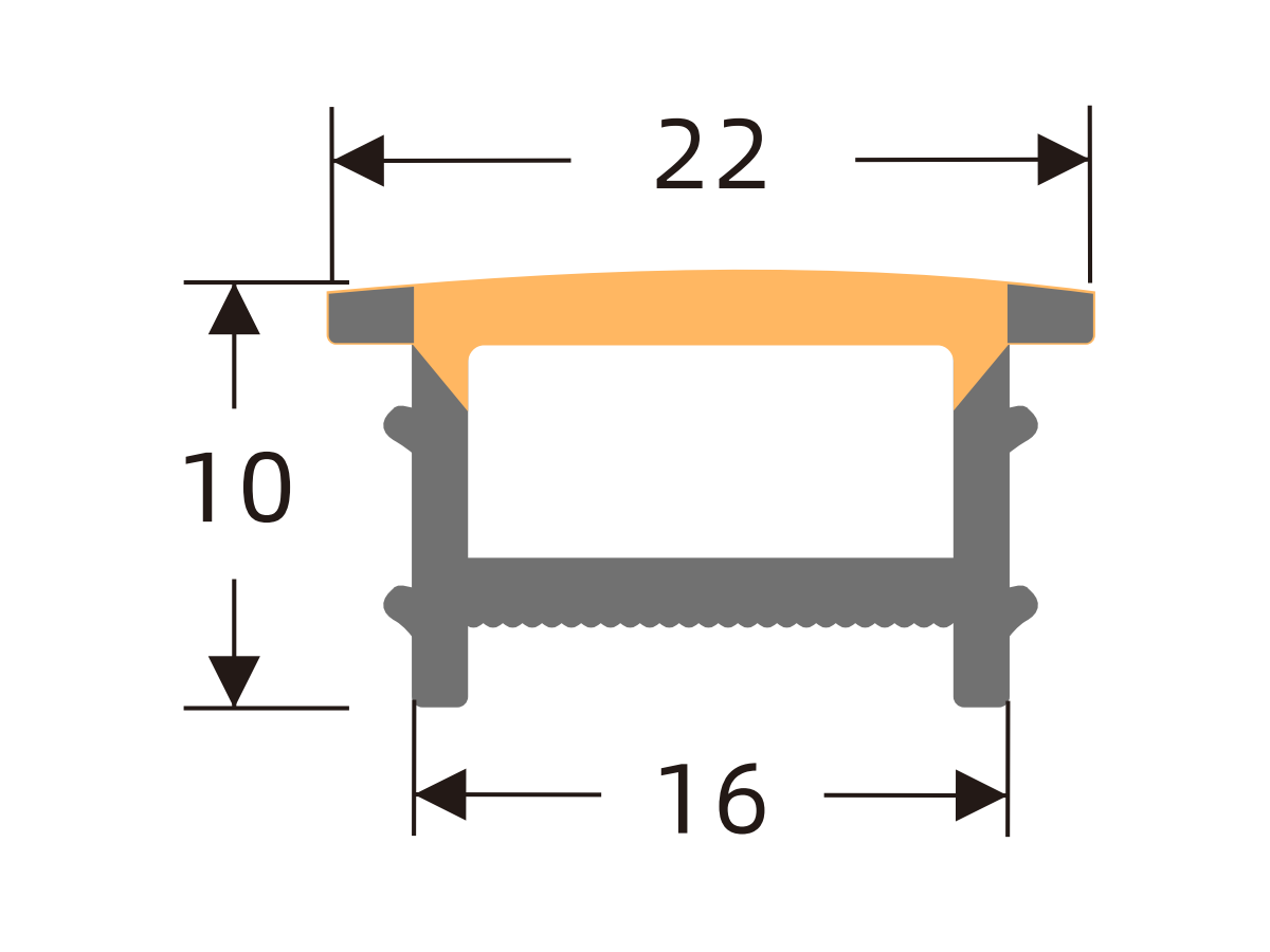
J1616 A
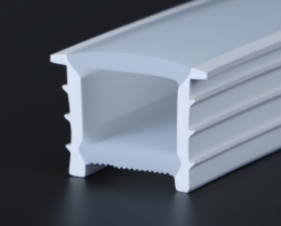
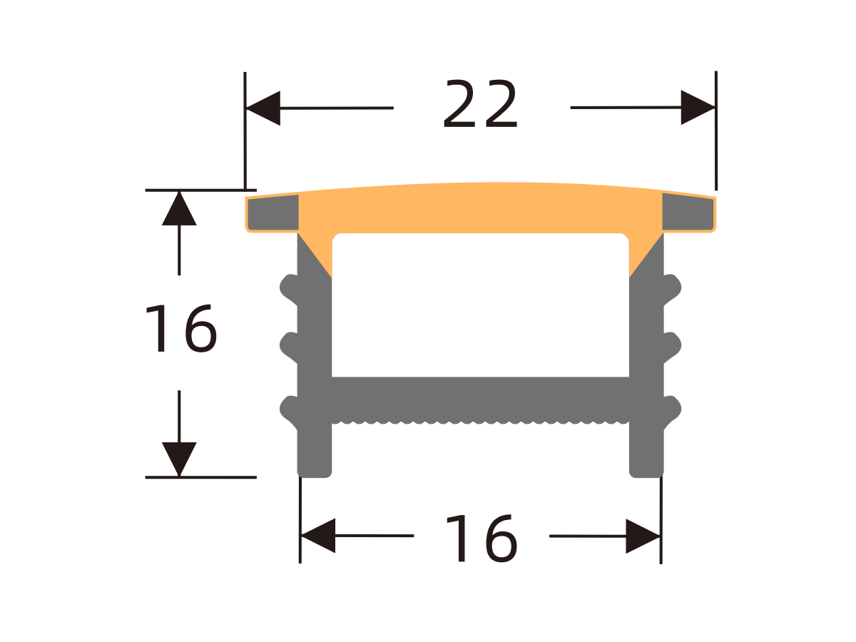
J1710 A
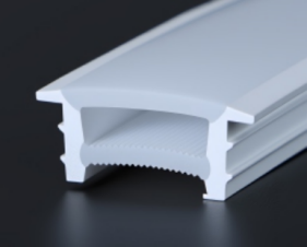
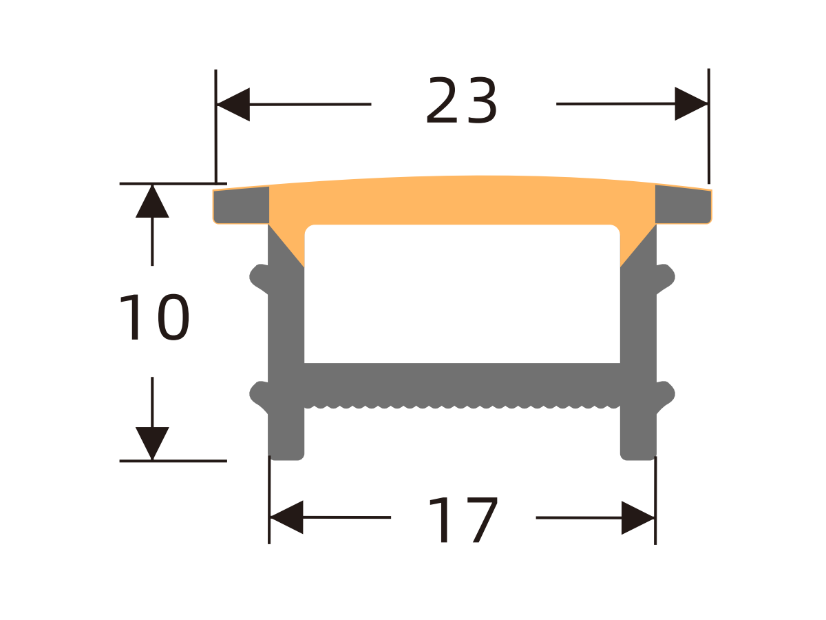
J1810 A
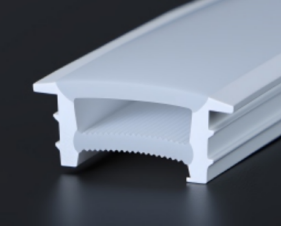
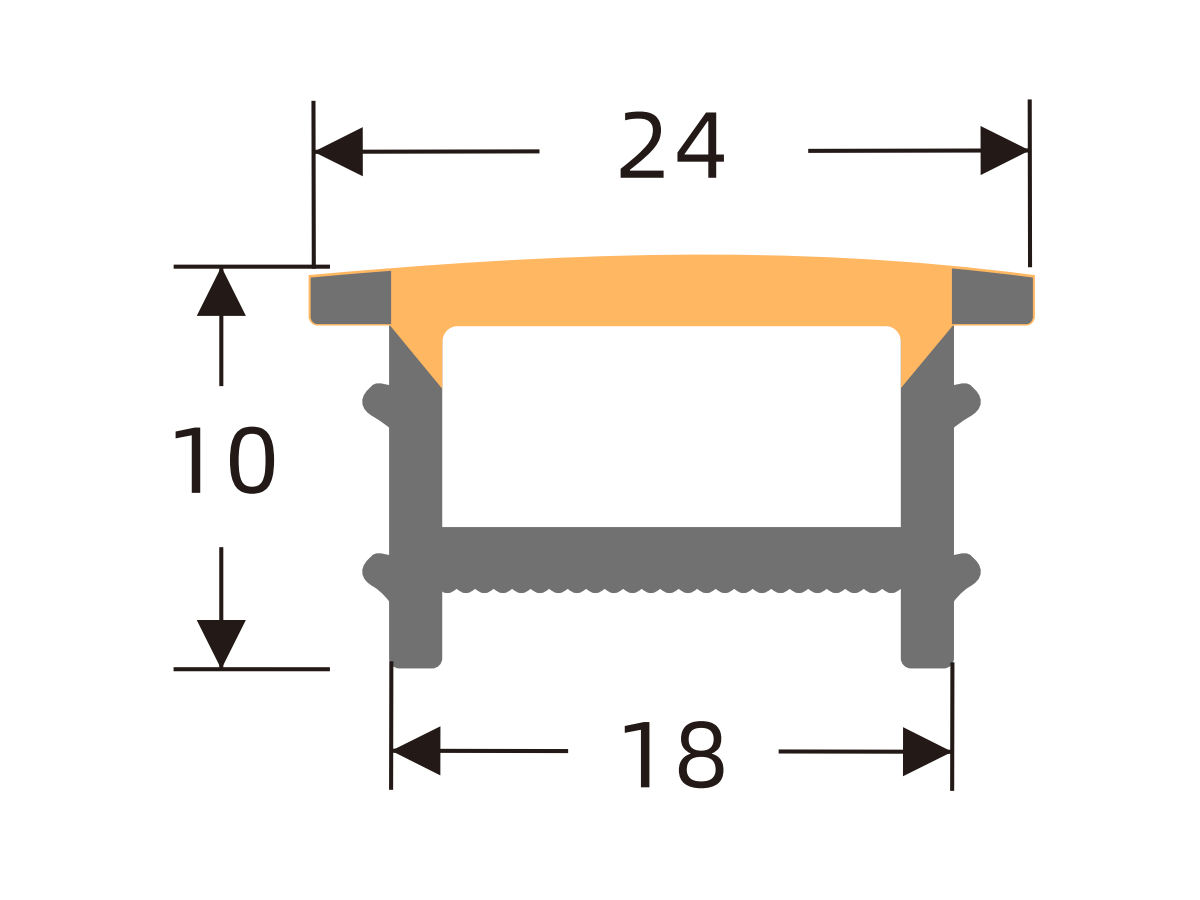
J2010 A
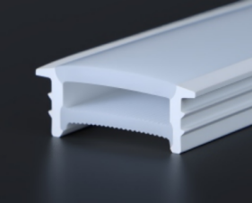
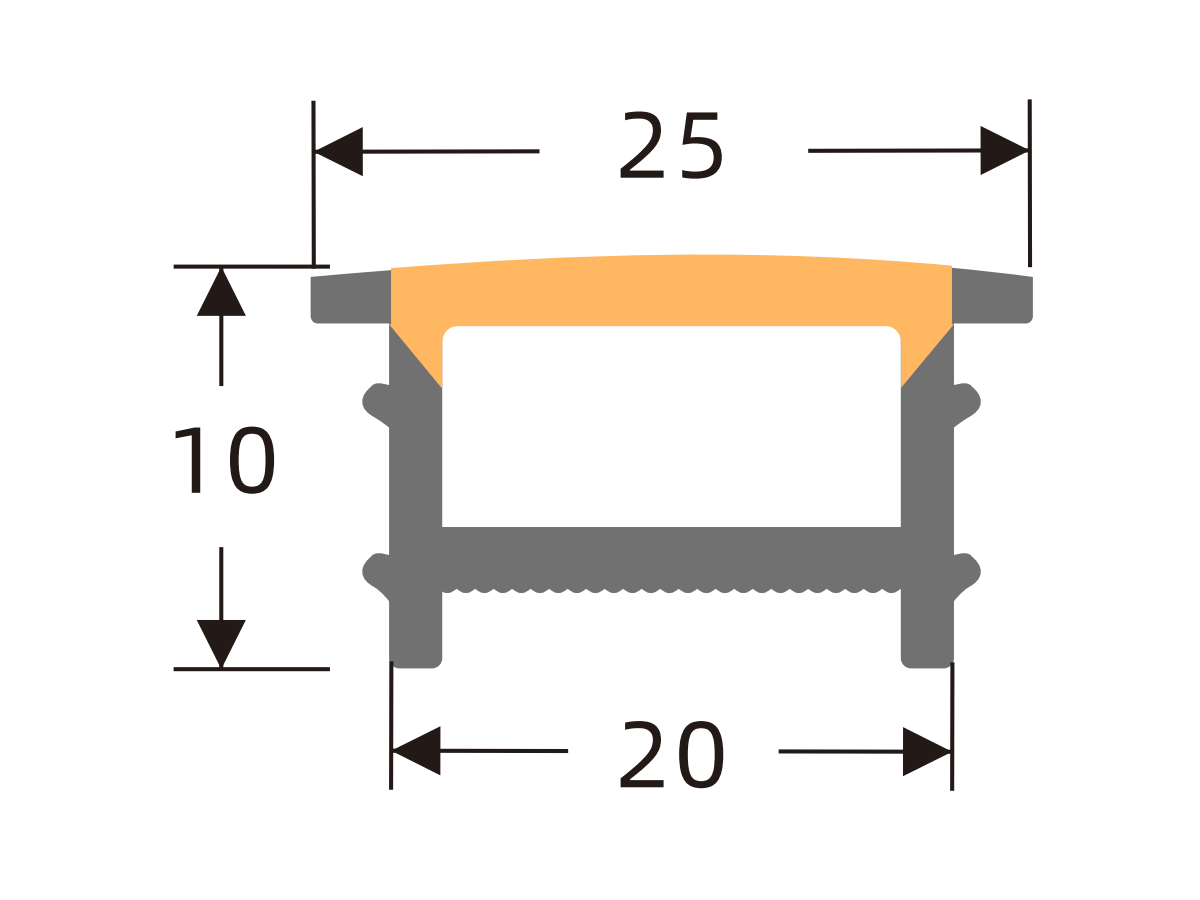
J2014 A
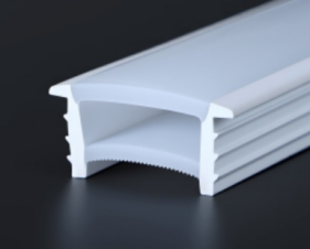
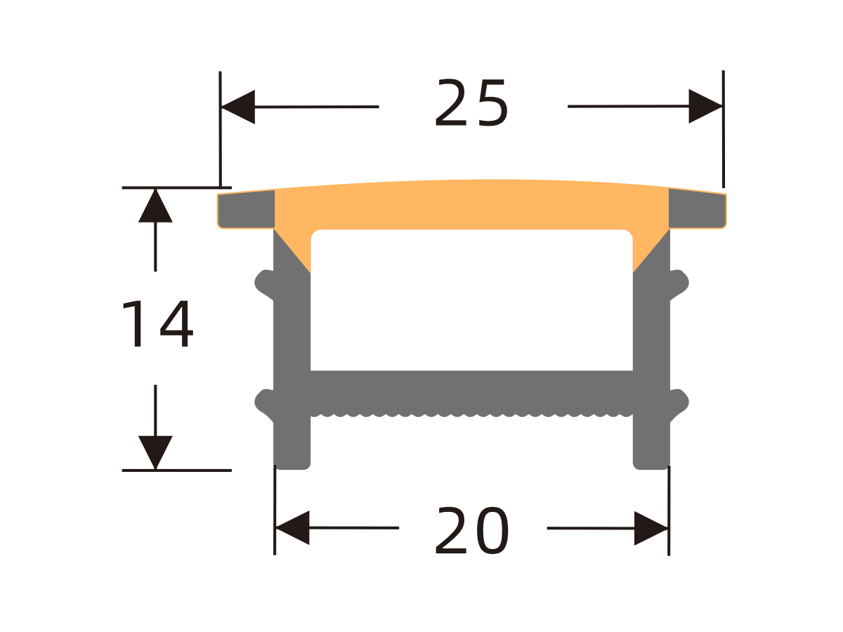
J2020 A
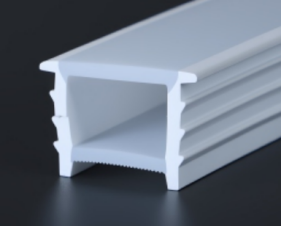
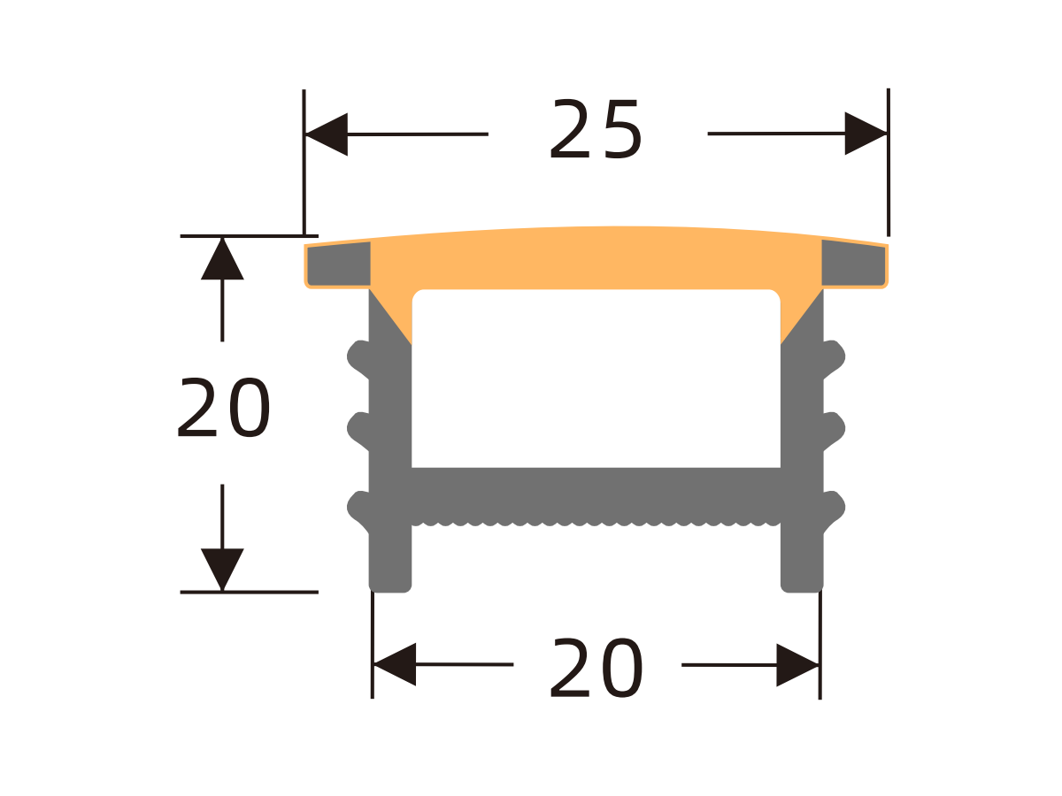
J2510 A
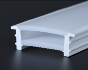
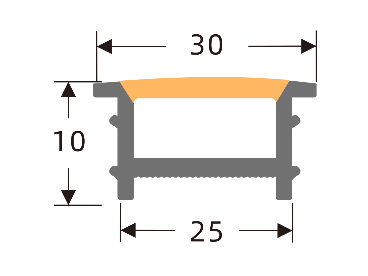
J2514 A
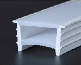
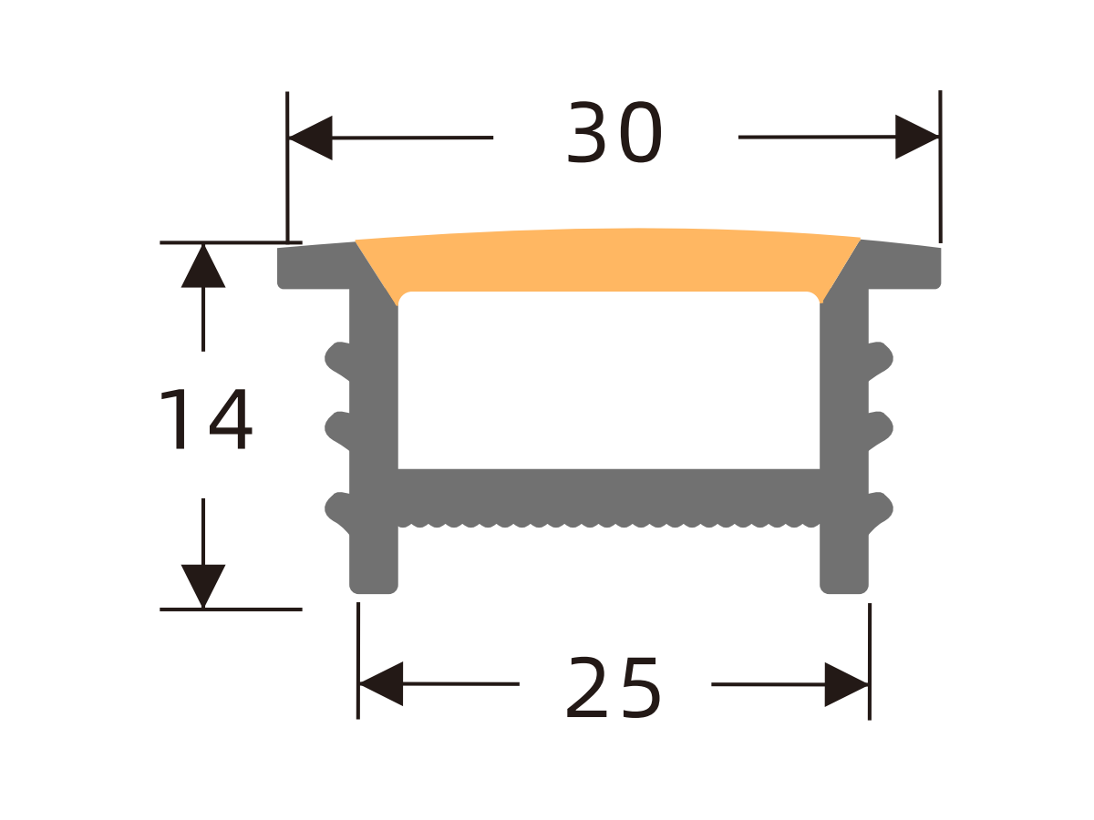
J2520 A
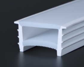
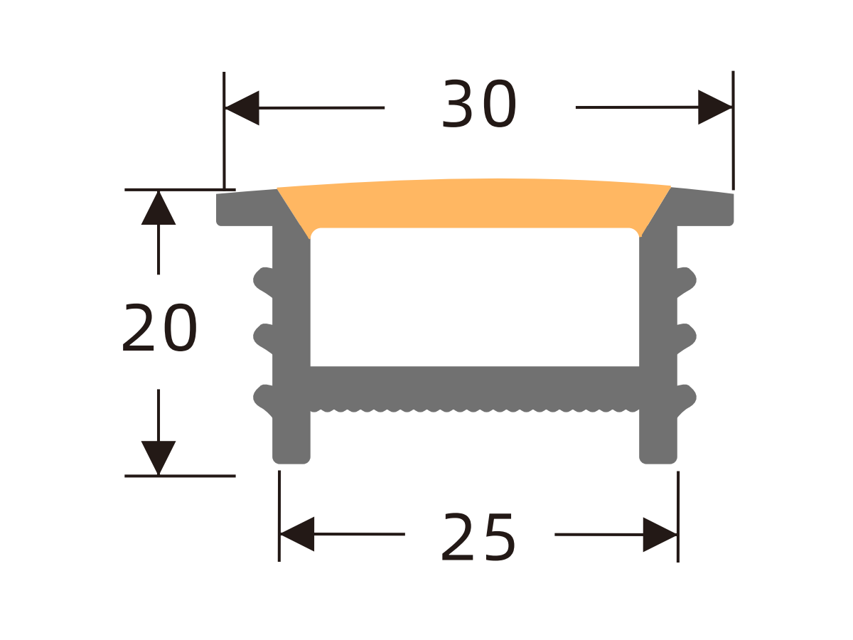
J3010 A
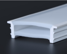
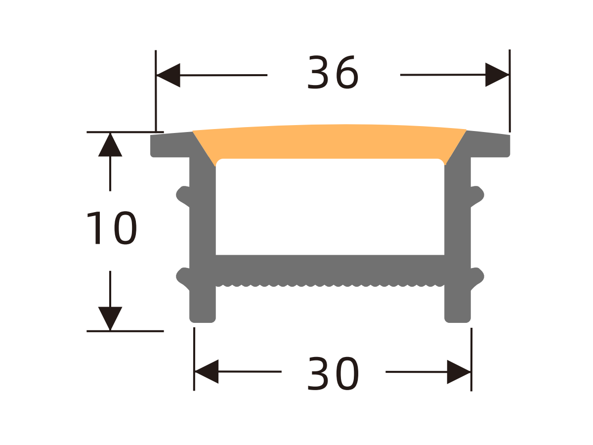
J3020 A
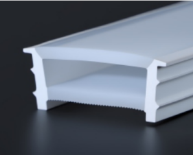
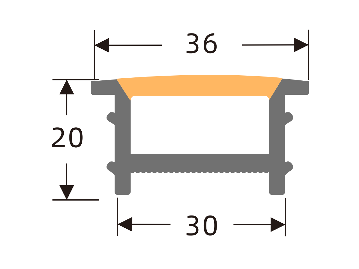
J3515 A
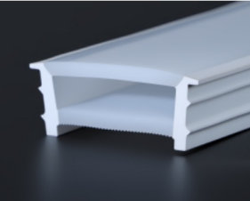
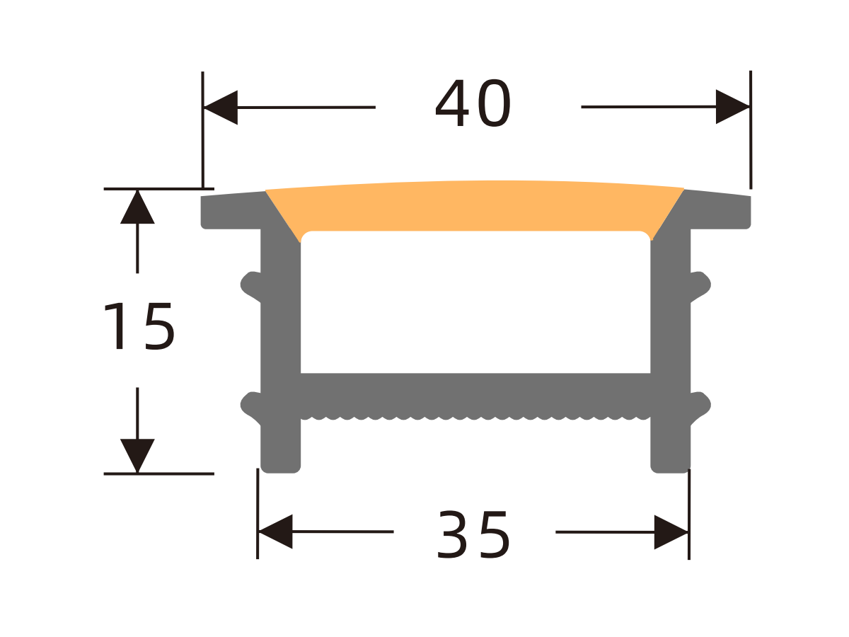
J4010 A
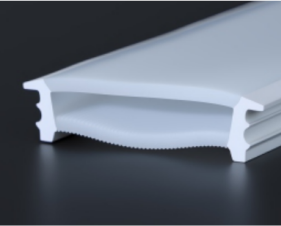
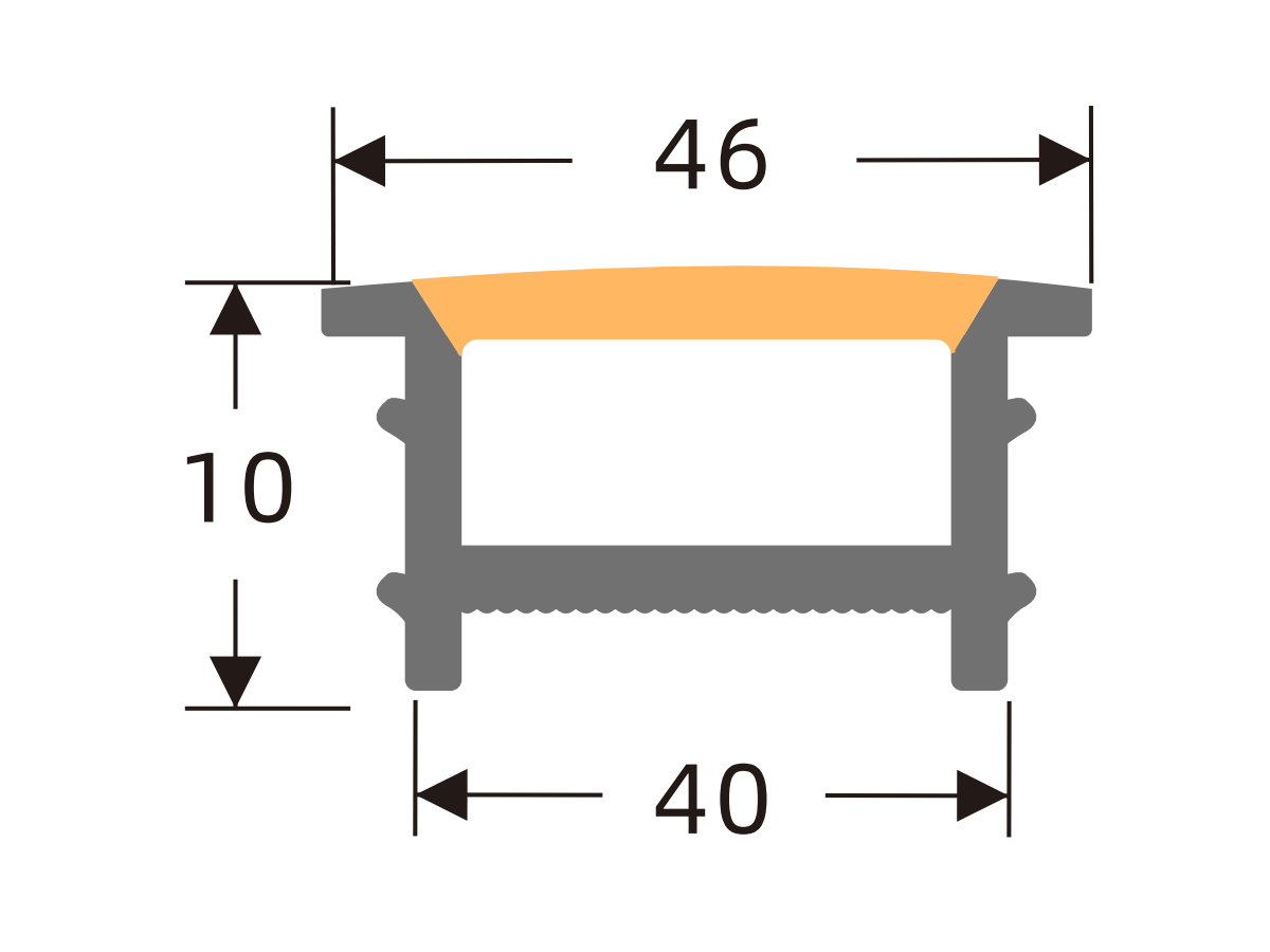
J4020 A
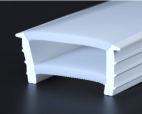
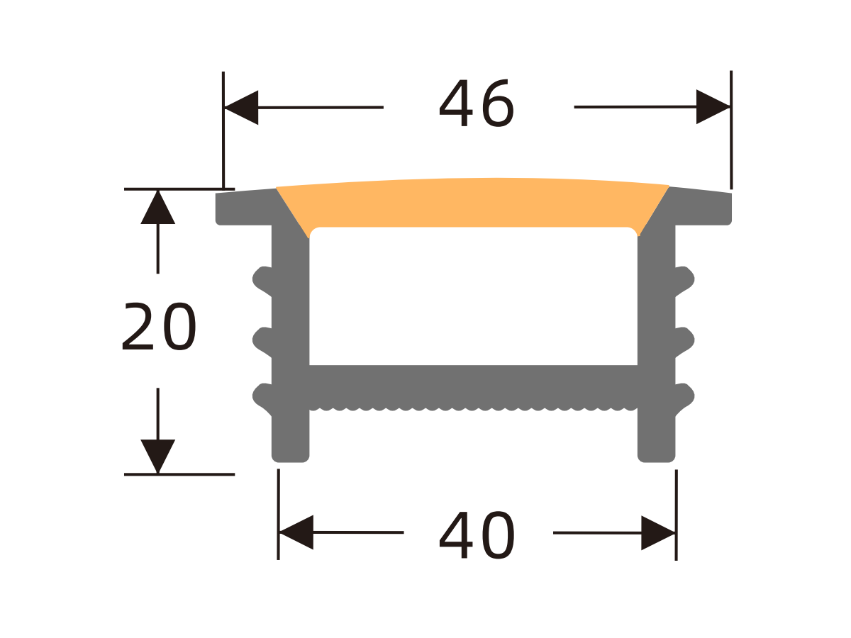
J5010 A
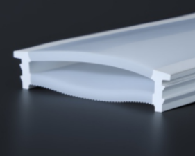
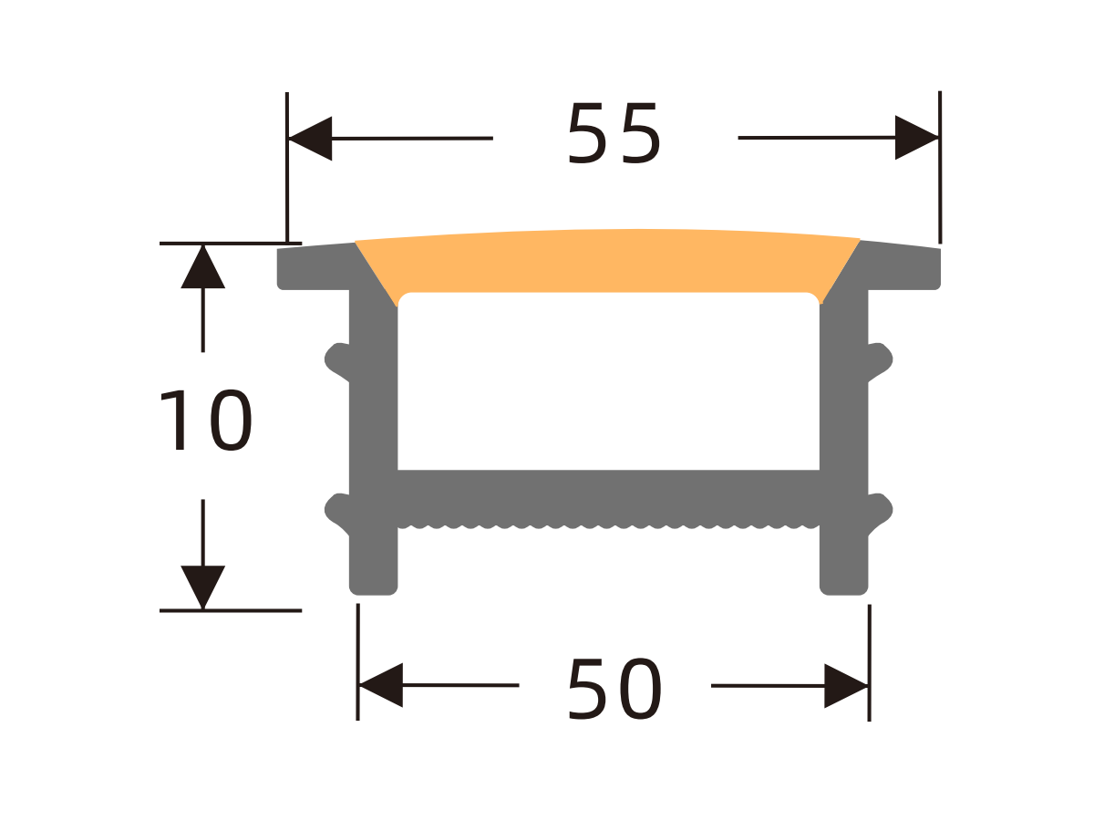
J5020 A
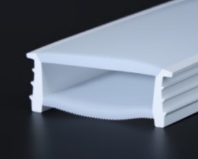
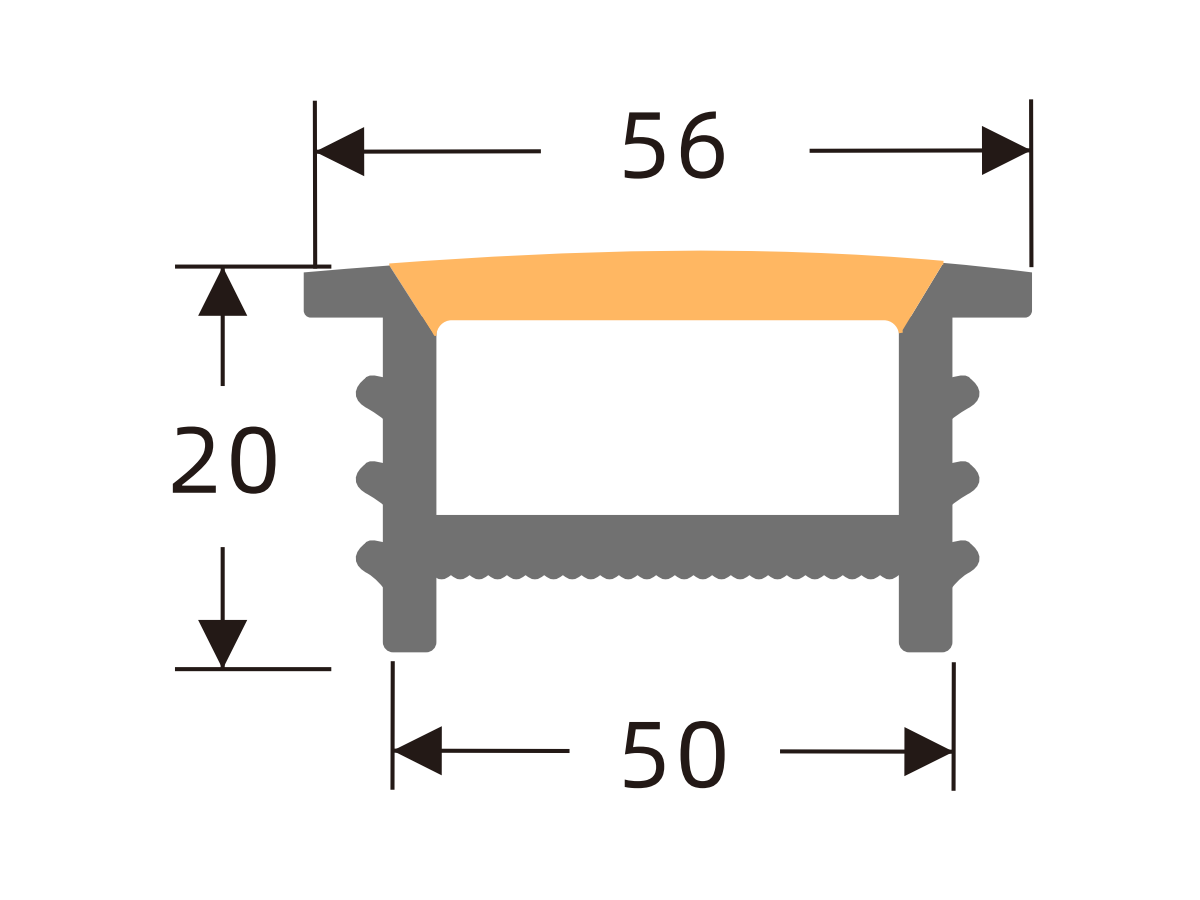
J6025 A
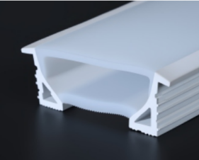
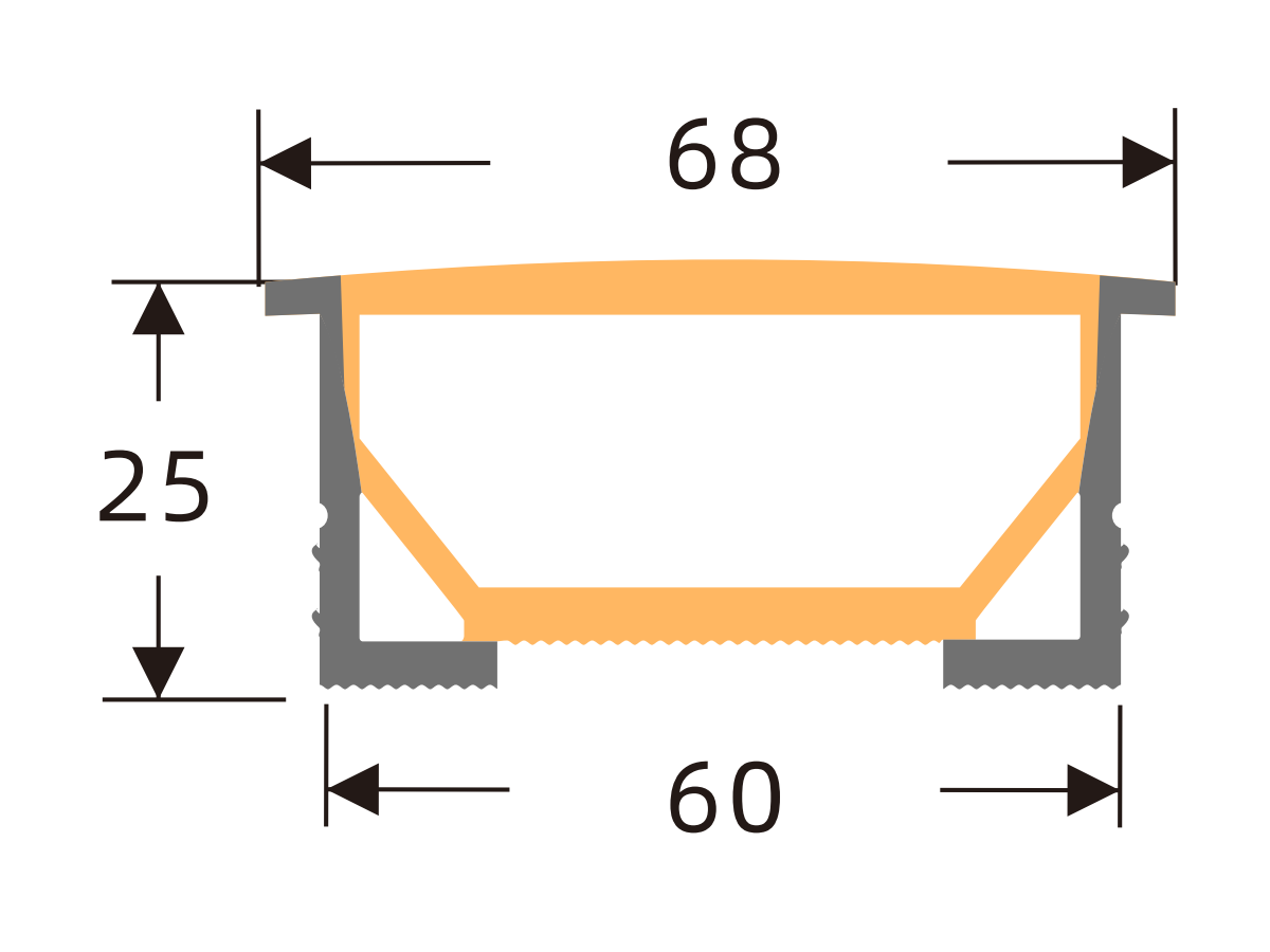
J7030 A
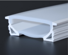
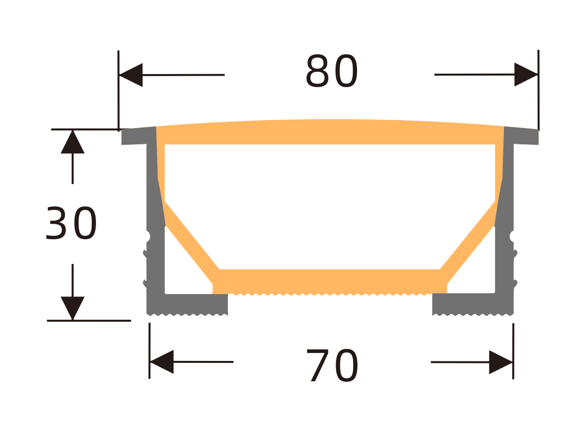
K0606 H
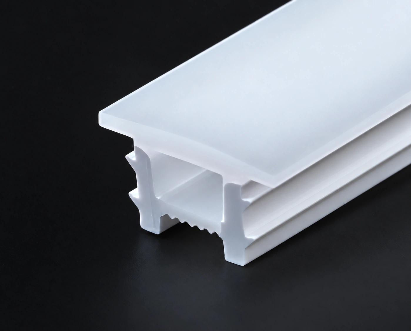
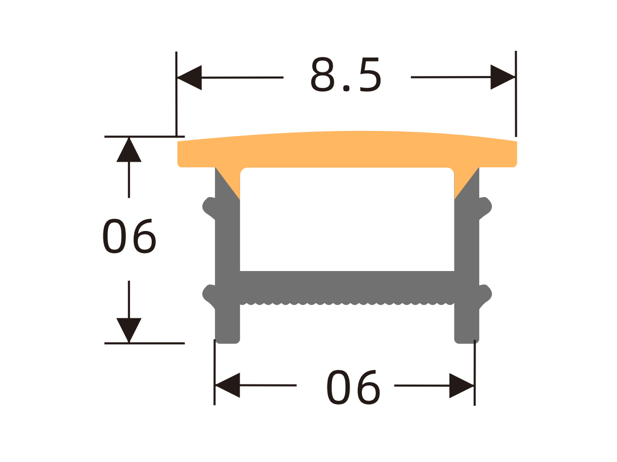
K0808 H
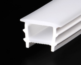
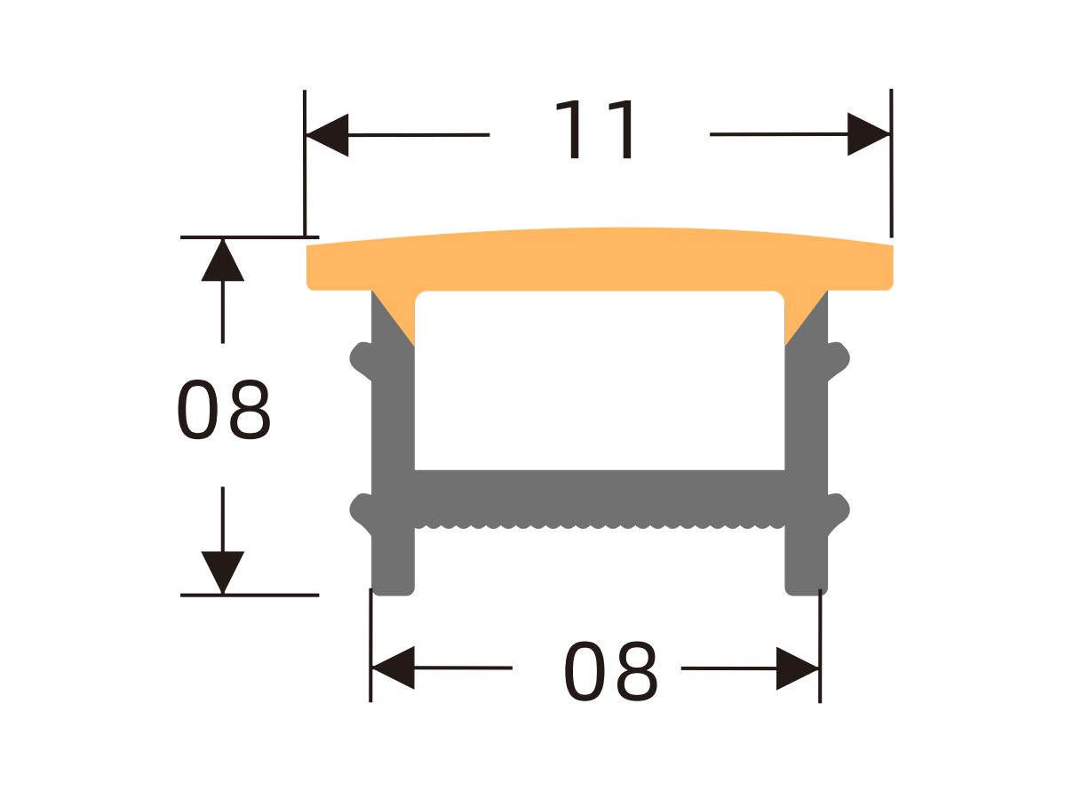
K1010 H
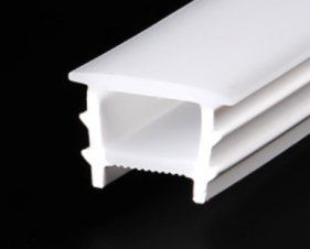
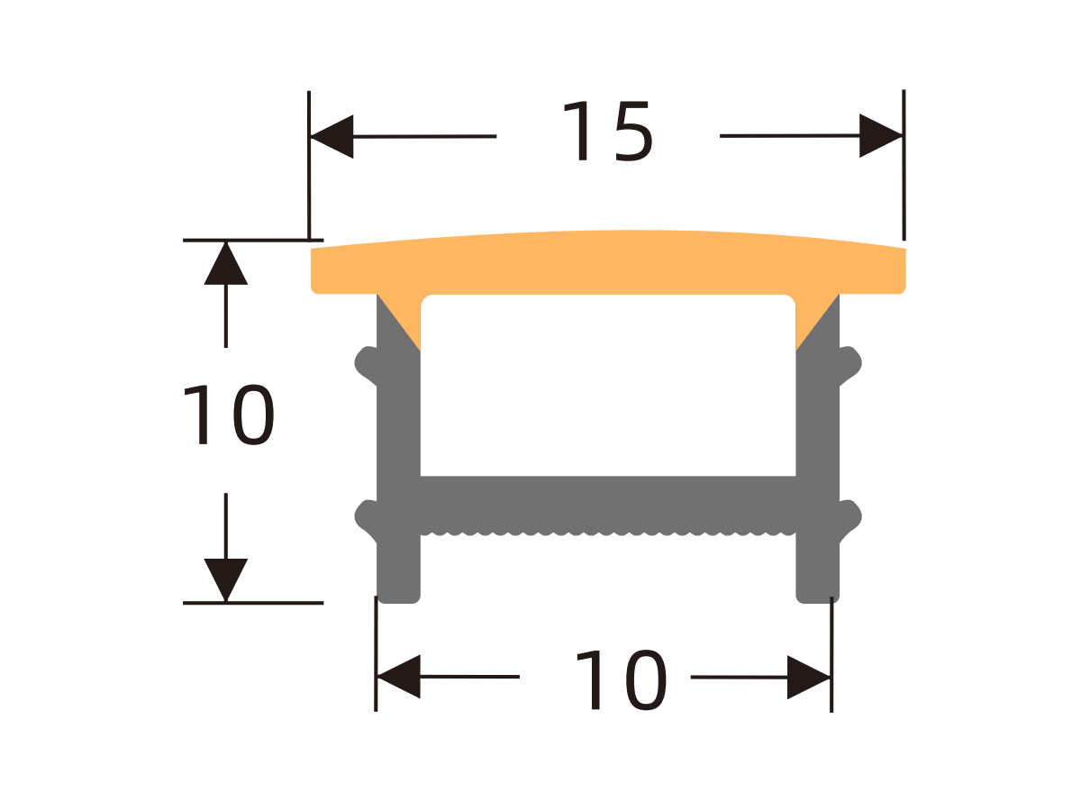
K1210 H
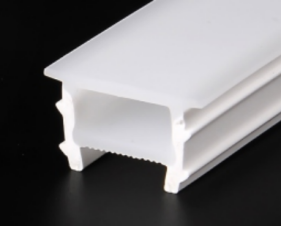
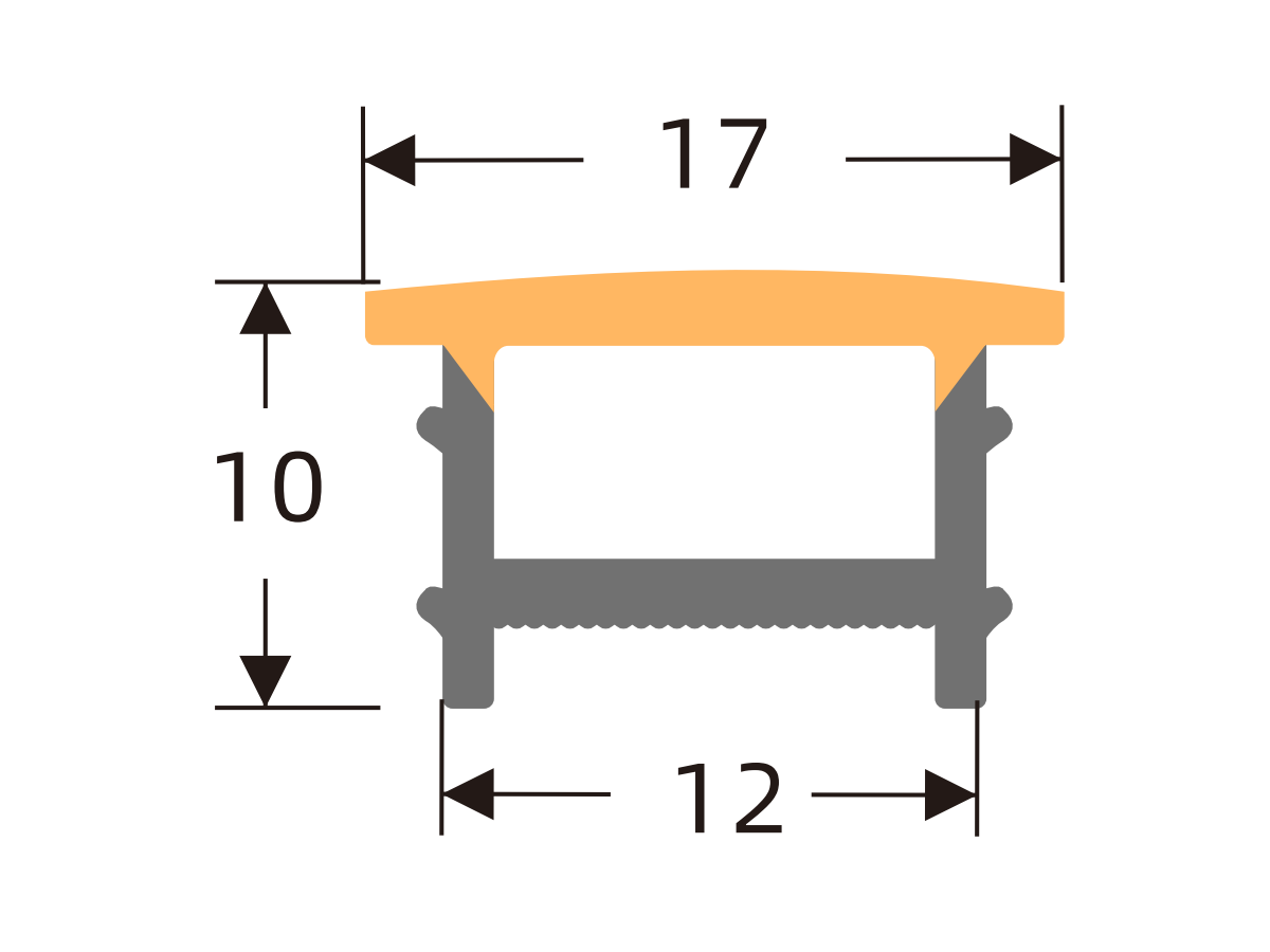
K1212 H
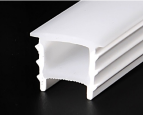
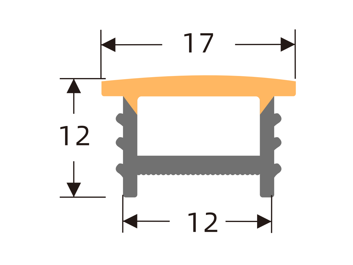
K1410 H
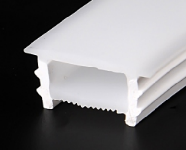
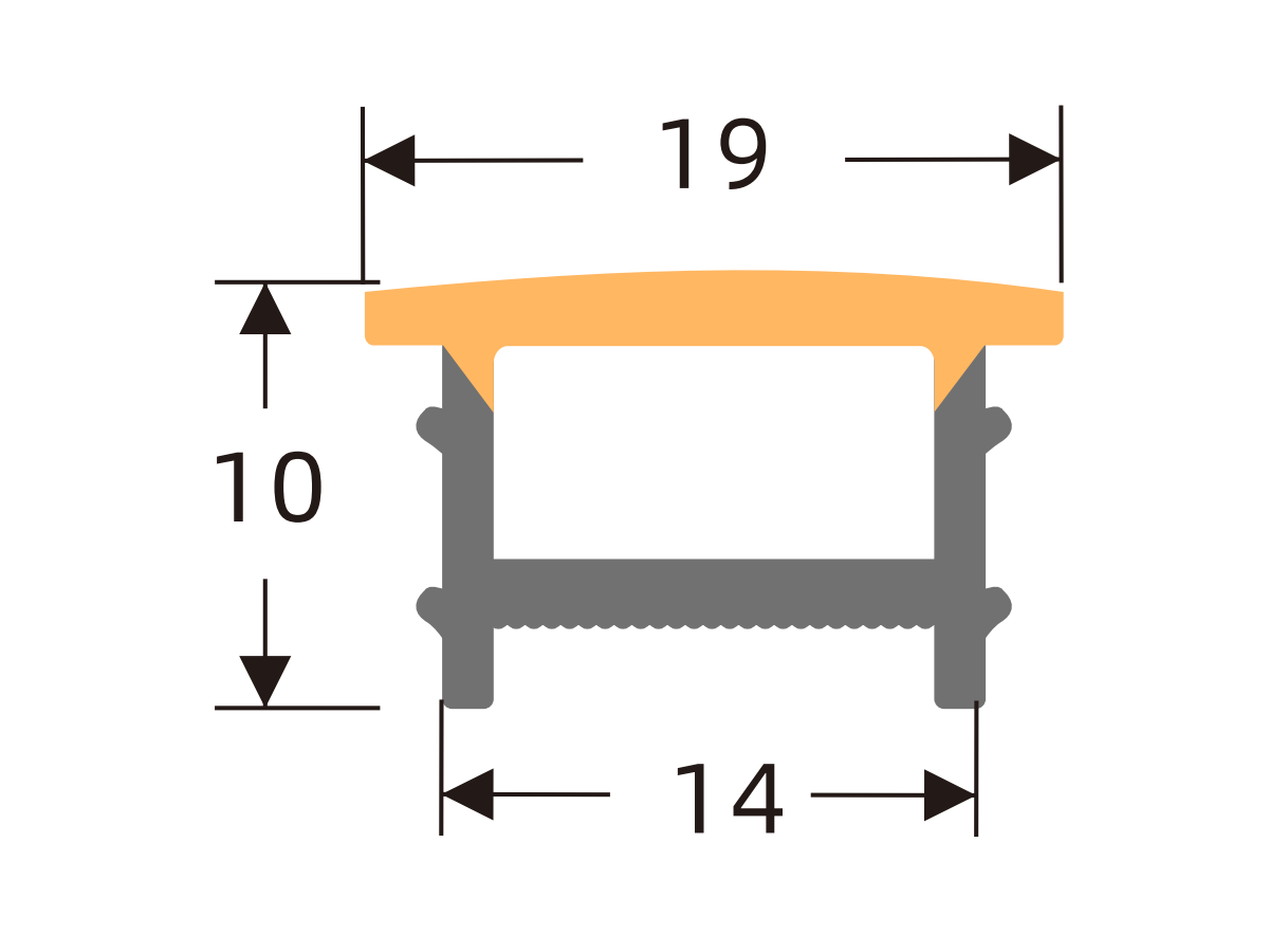
K1414 H
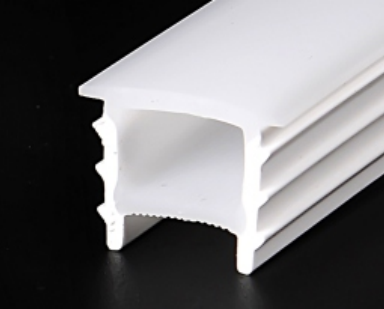
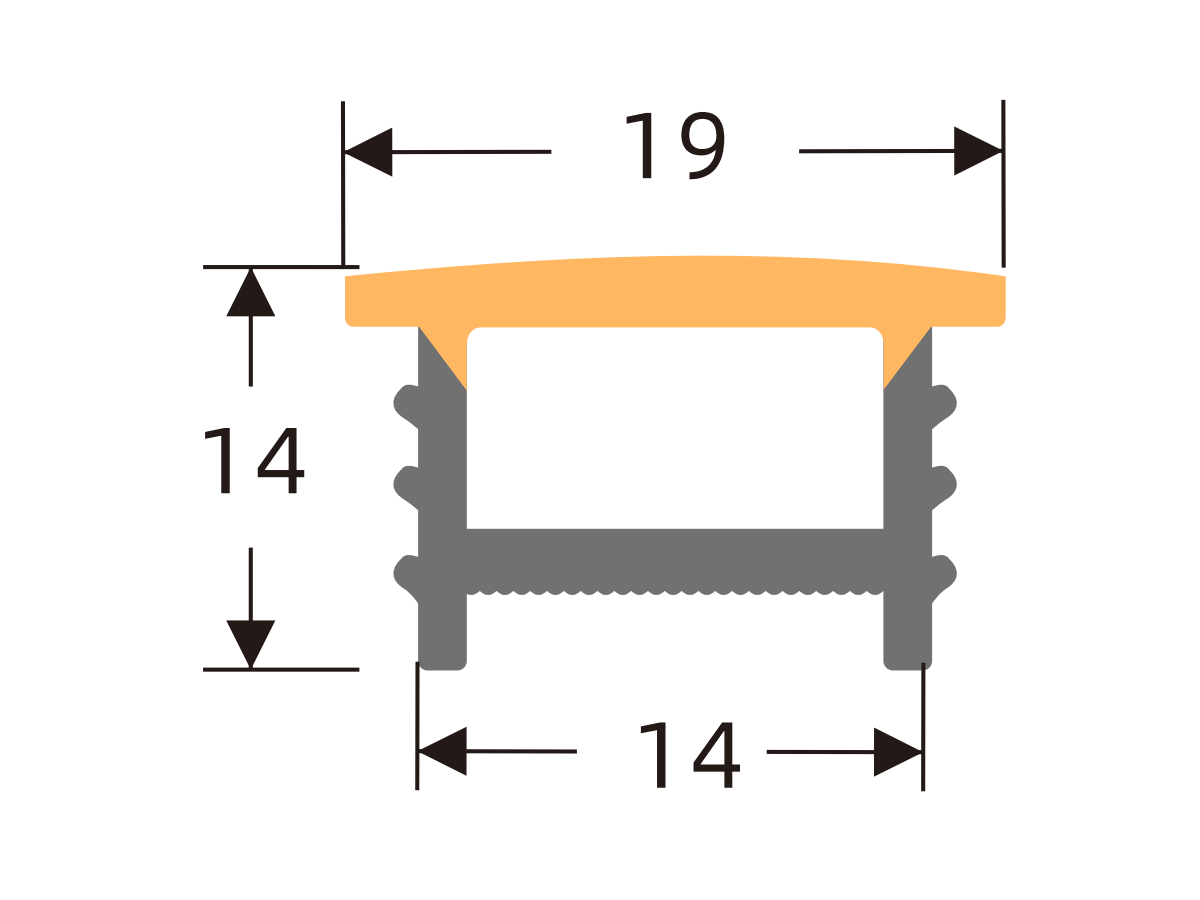
K1510 H
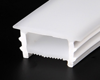
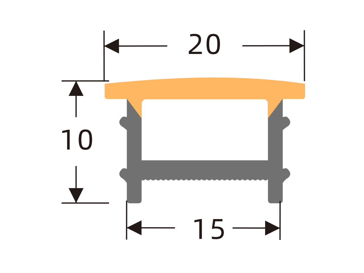
K1515 H
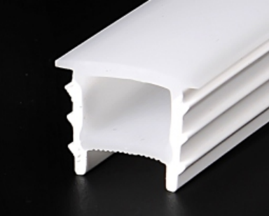
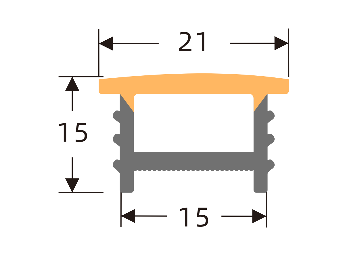
K1610 H
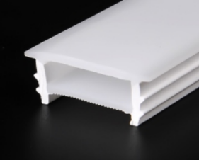
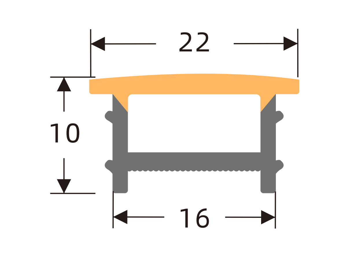
K1616 H
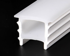
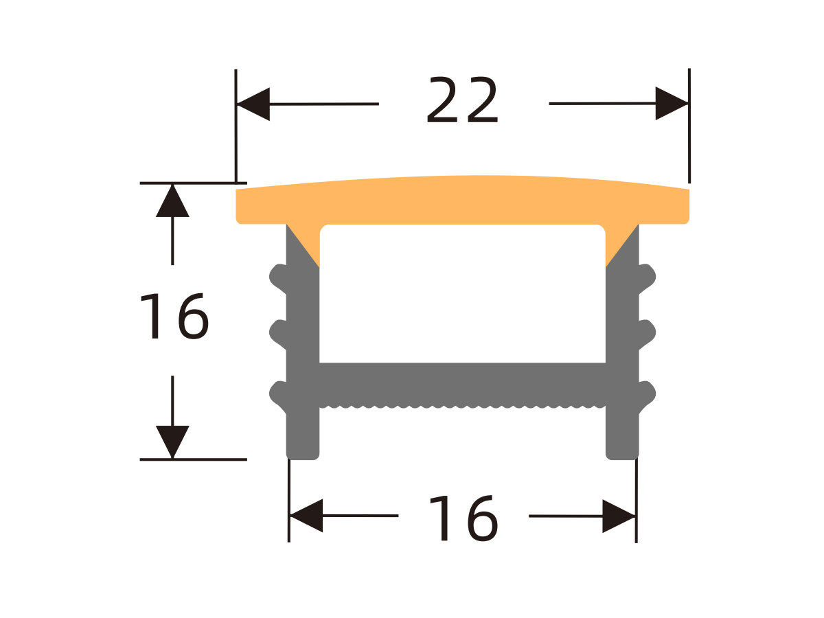
K1710 H
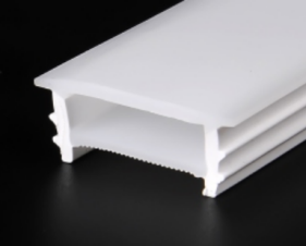
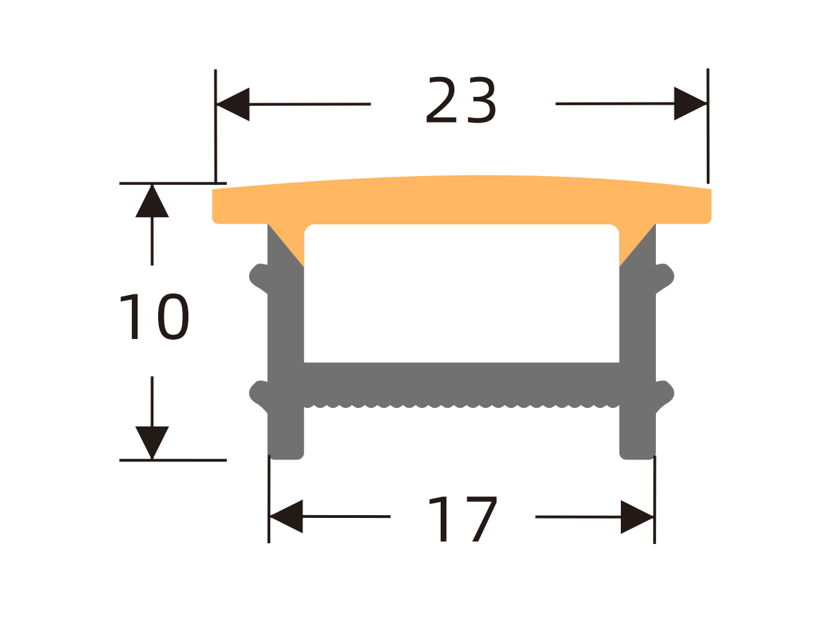
K1810 H
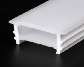
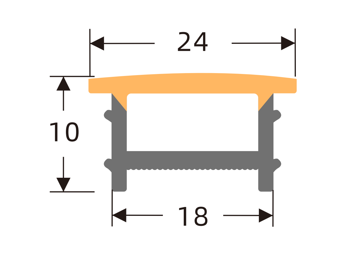
K2010 H
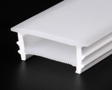
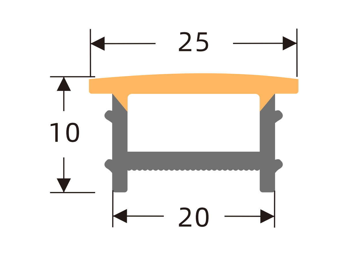
K2014 H
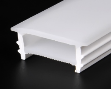
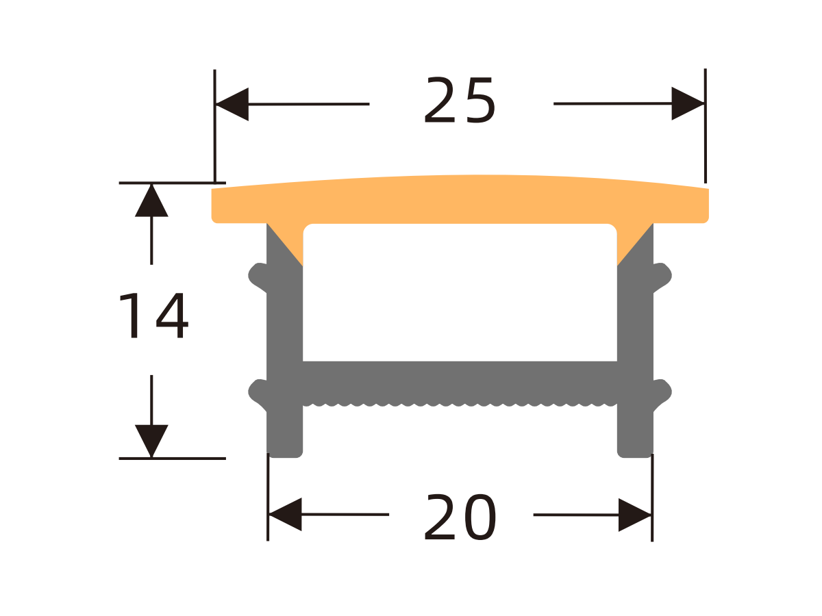
K2020 H
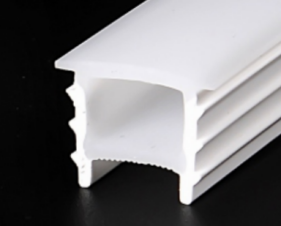
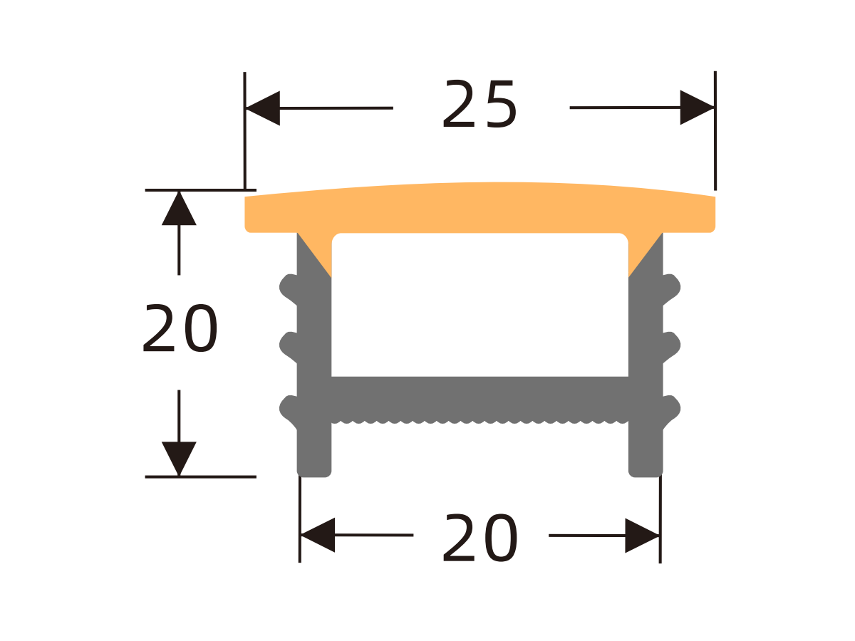
K2310 H
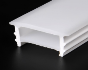
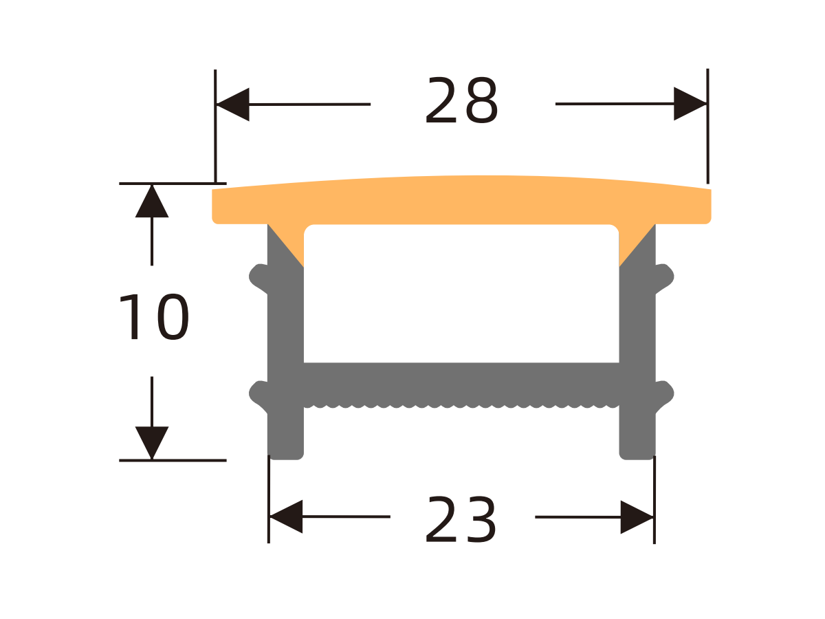
K2510 H
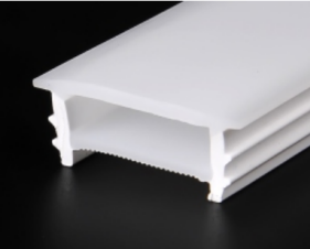
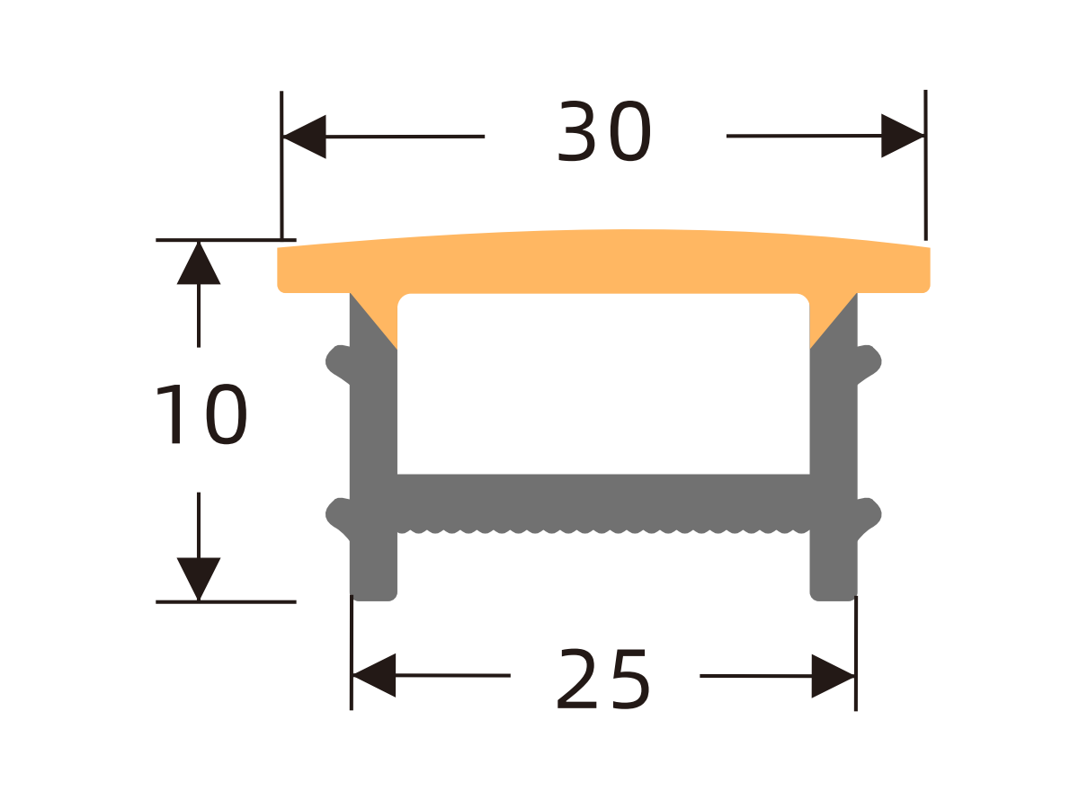
K2514 H
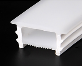
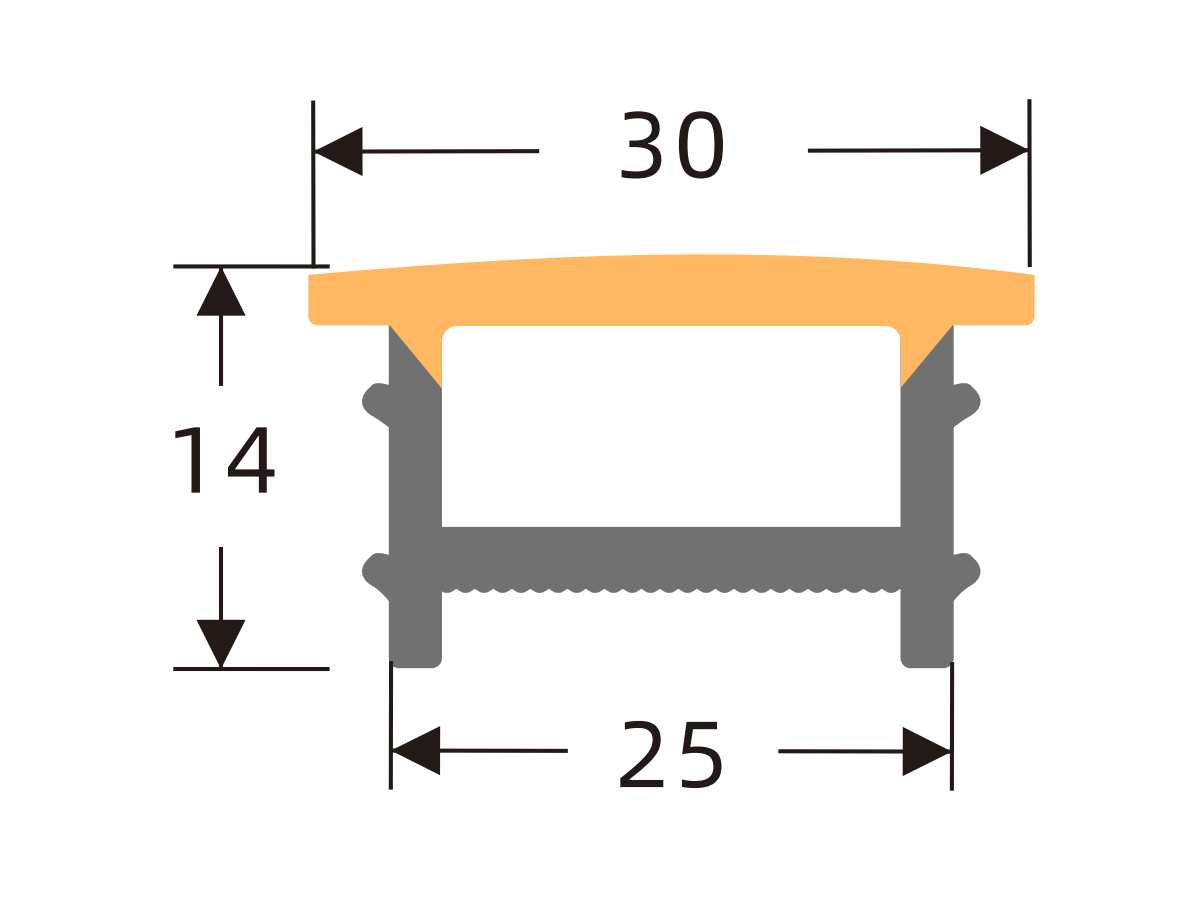
K2517 H
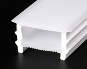
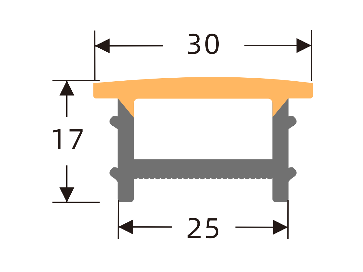
K2520 H
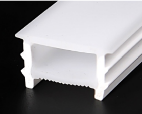
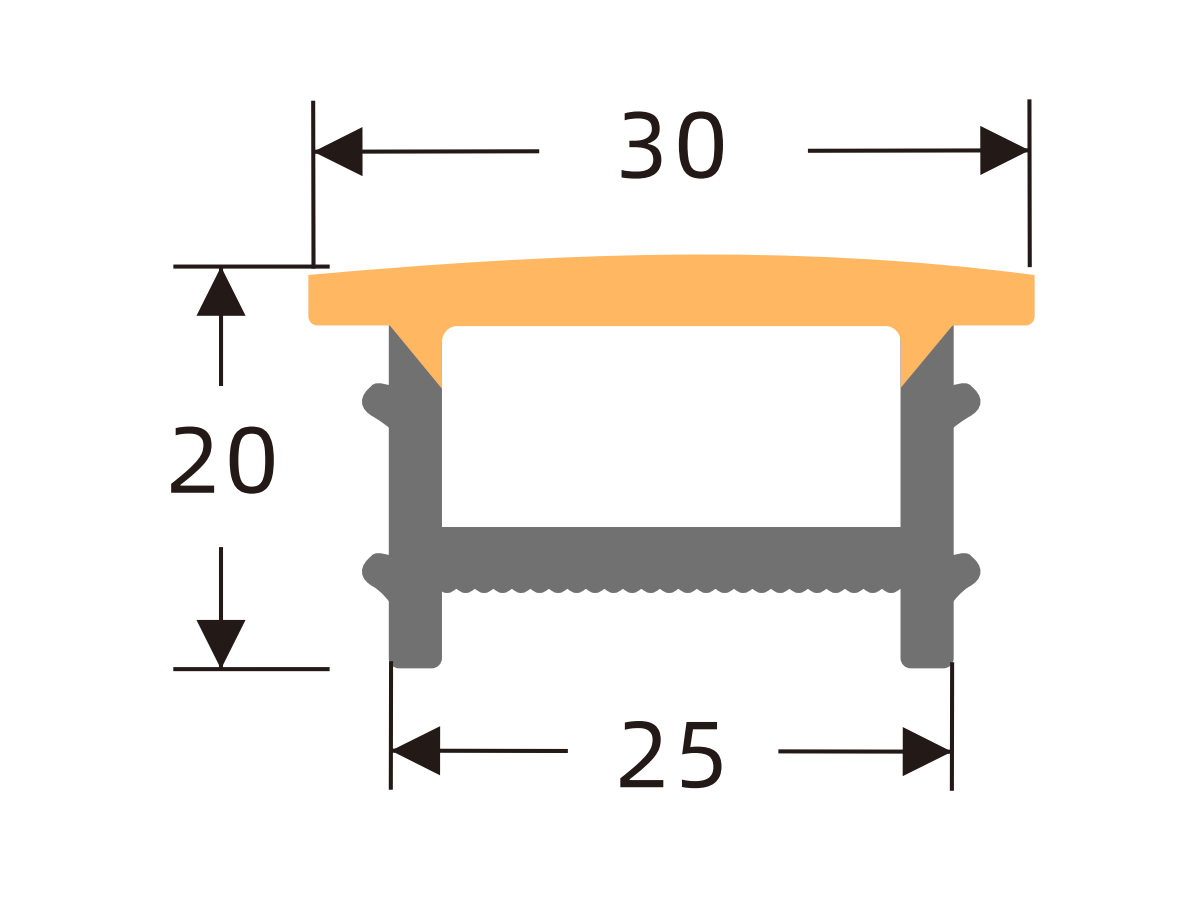
K3010 H
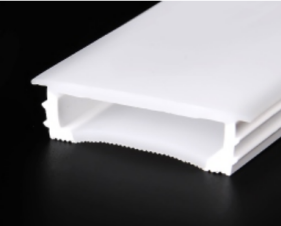
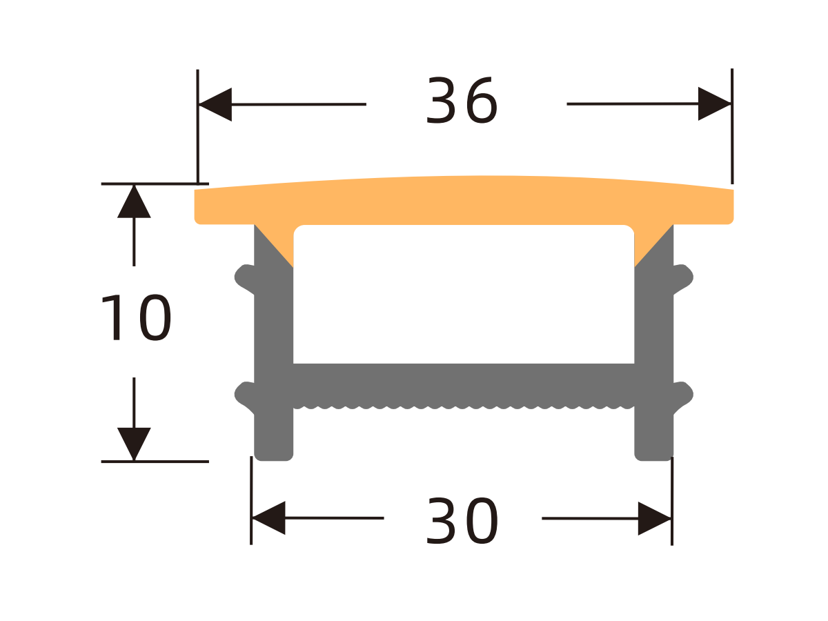
K3020 H
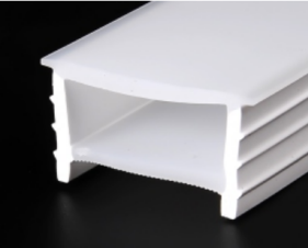
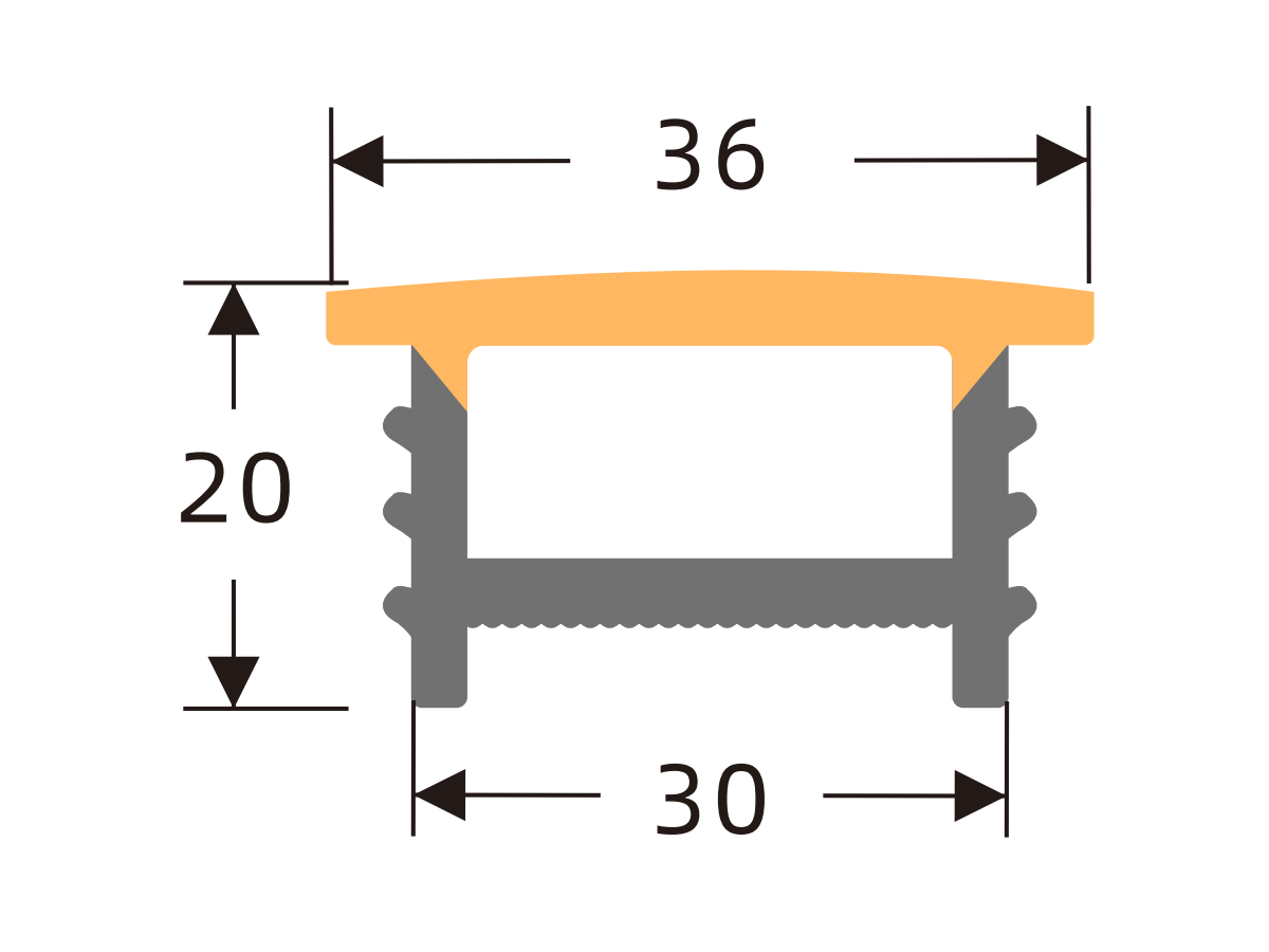
K3510 H
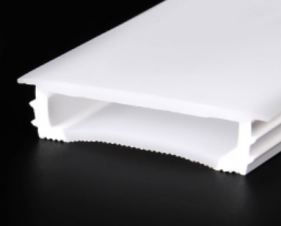
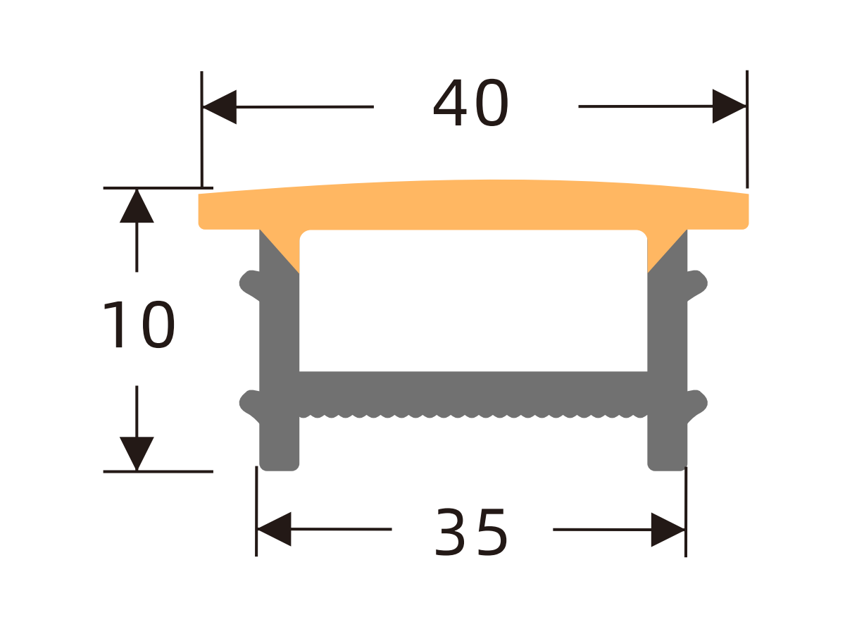
K4010 H
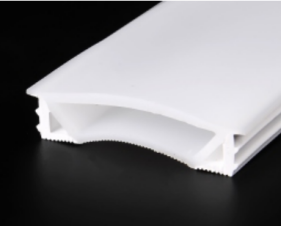
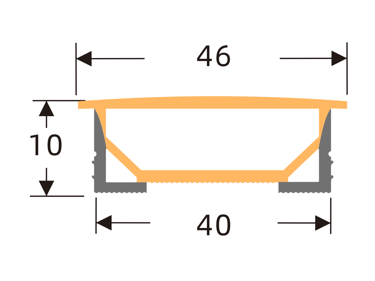
K4020 H
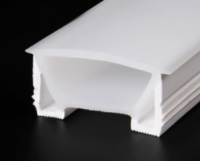
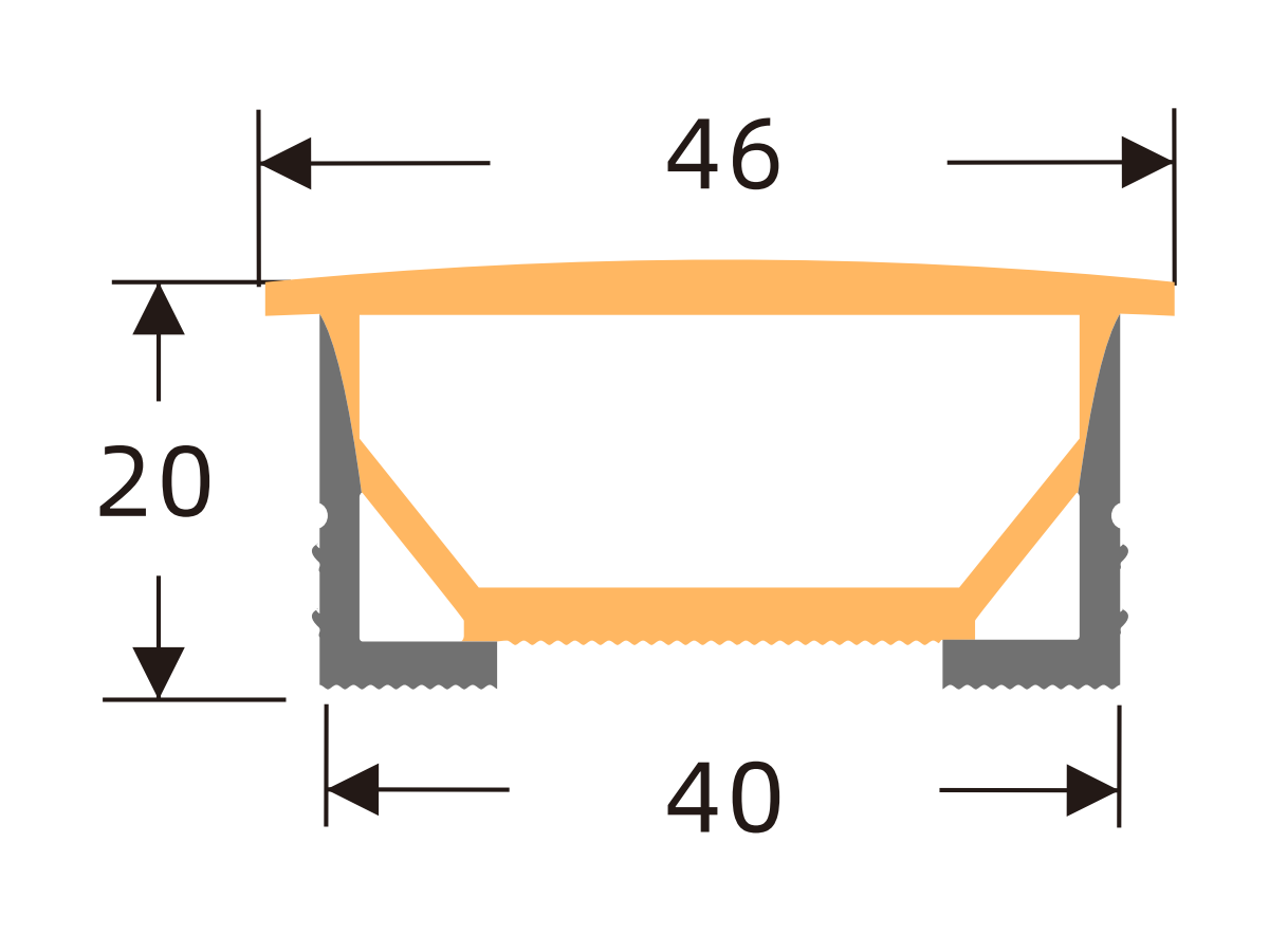
K5010 H
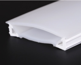
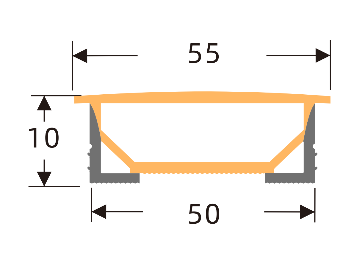
K5020 H
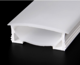
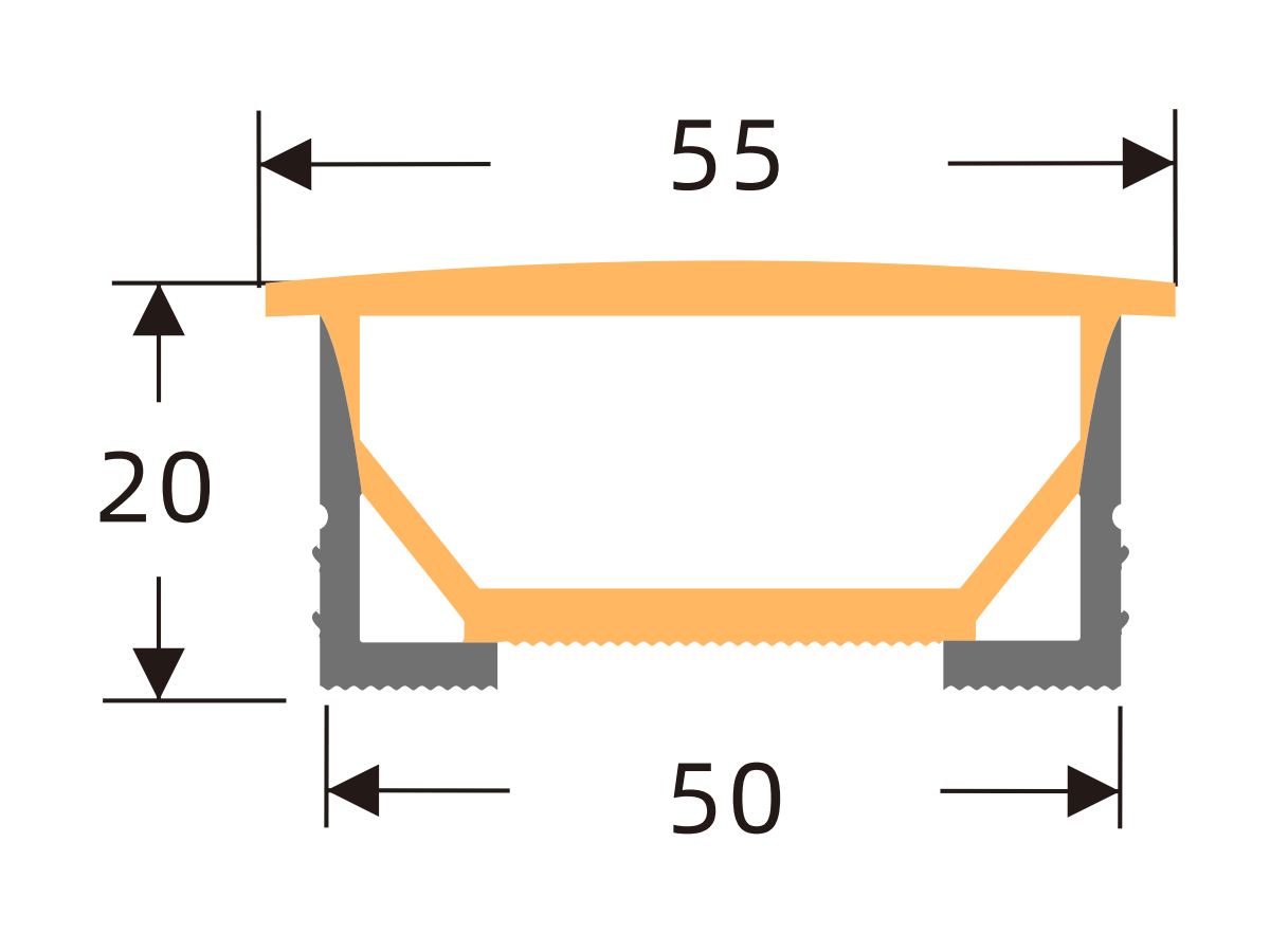
K6020 H
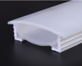
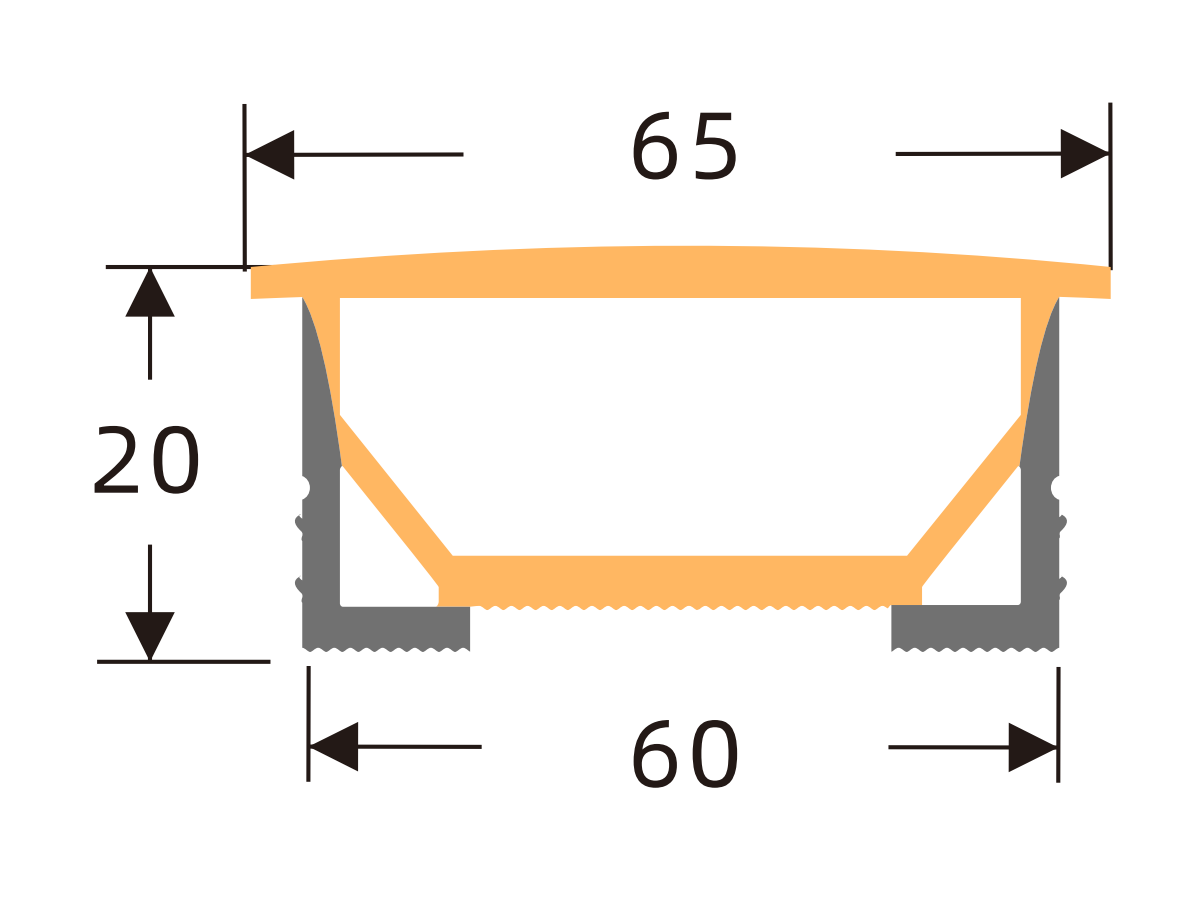
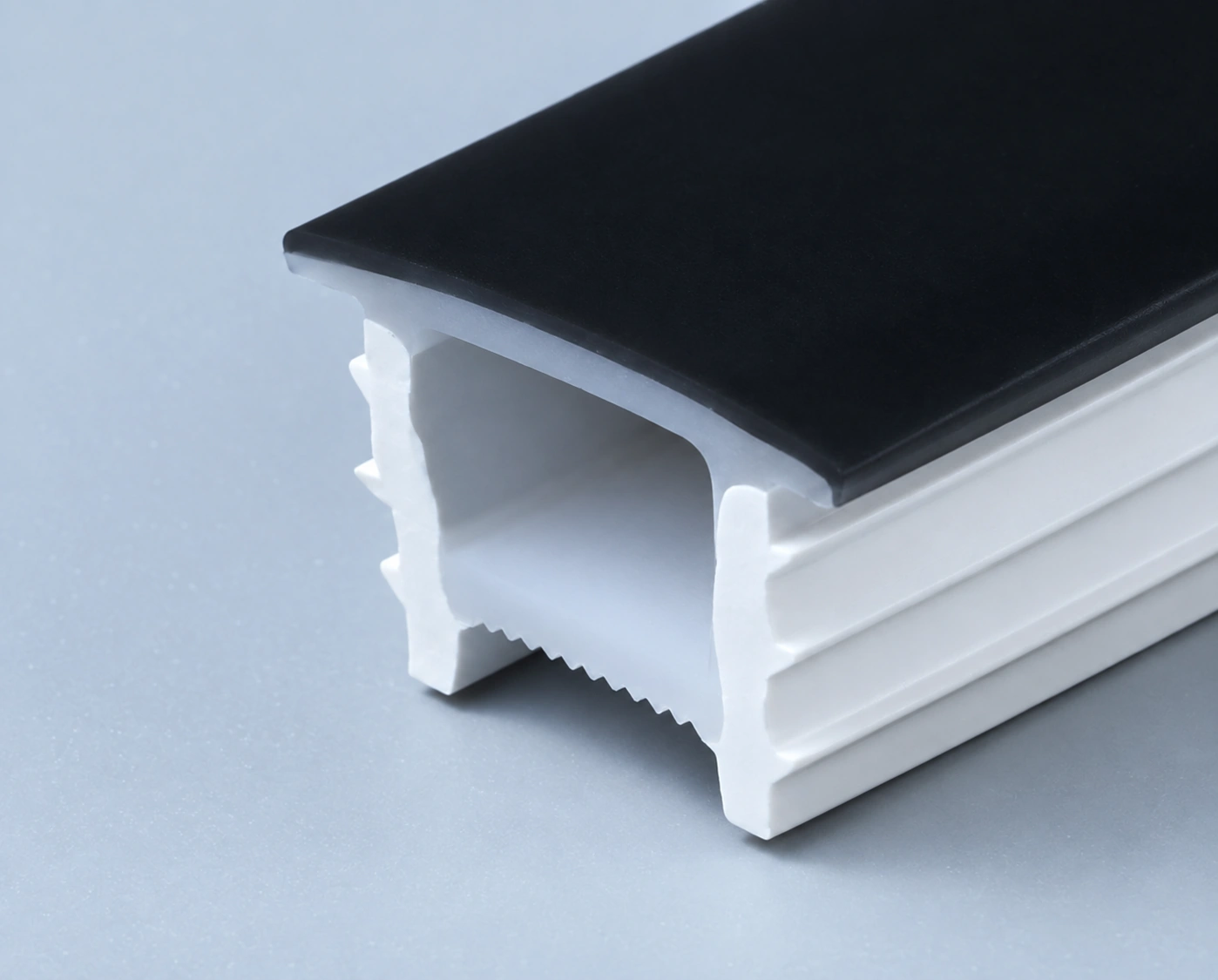
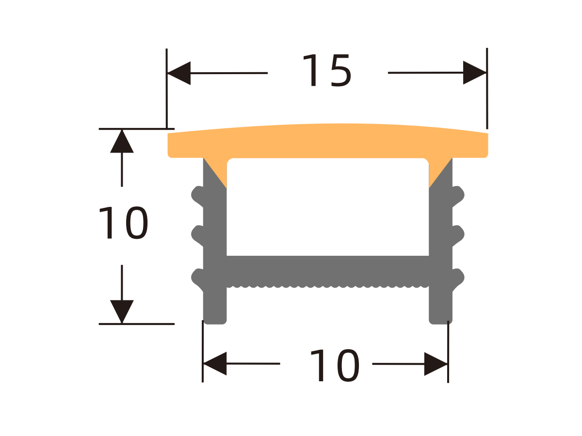
L1010
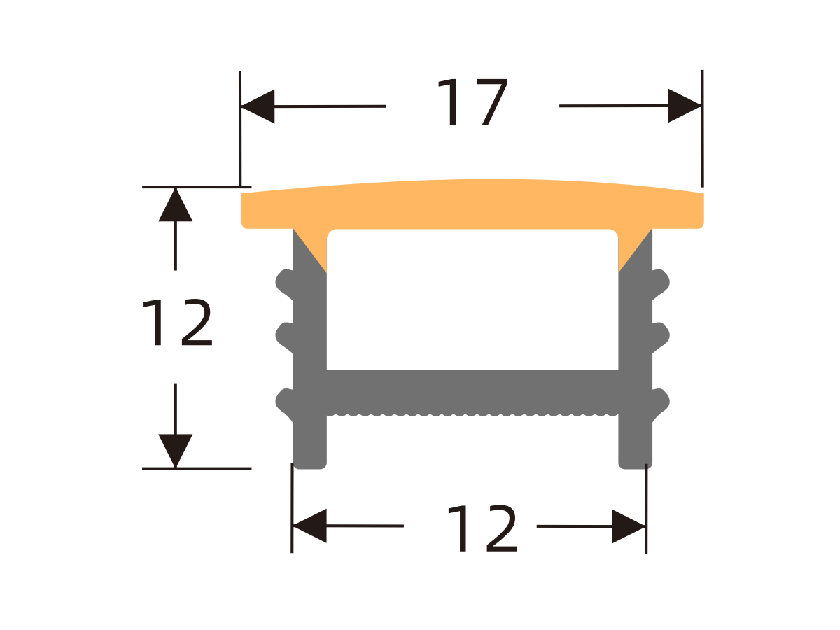
L1212
L1414
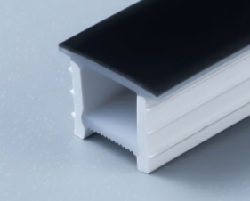
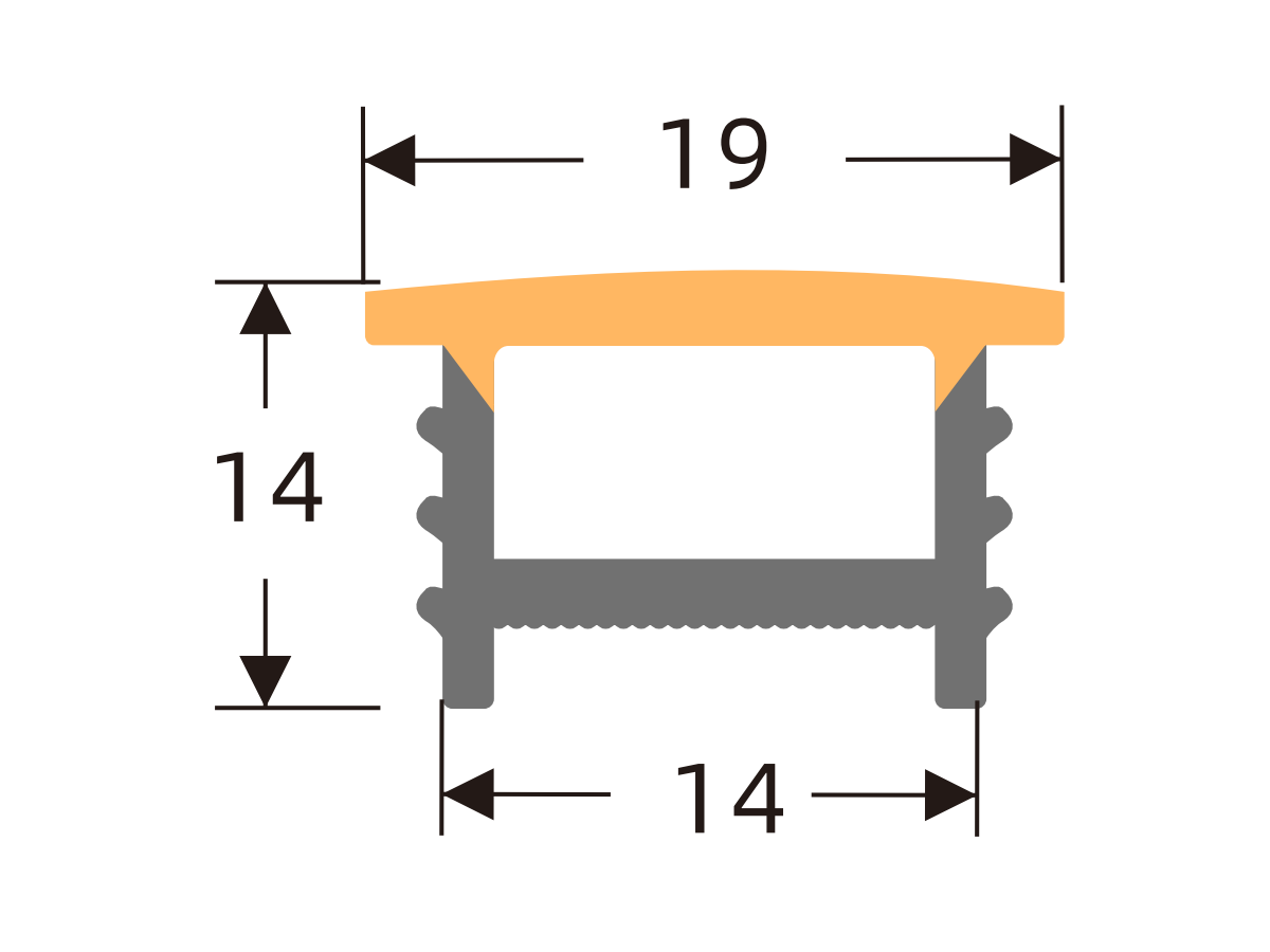
L1510
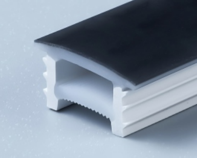
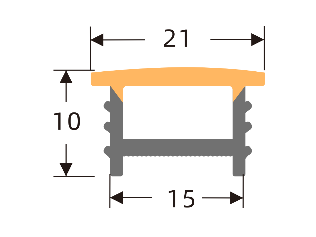
L1610
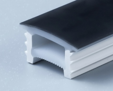
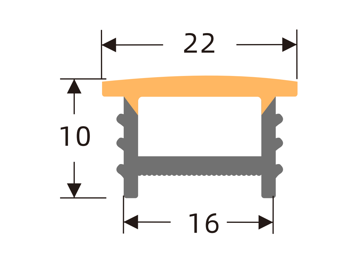
L1616
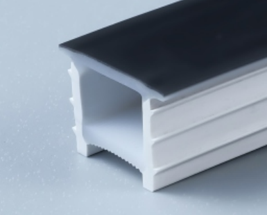
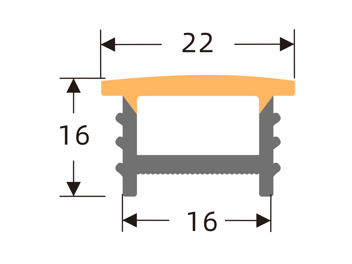
L2010
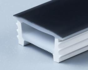
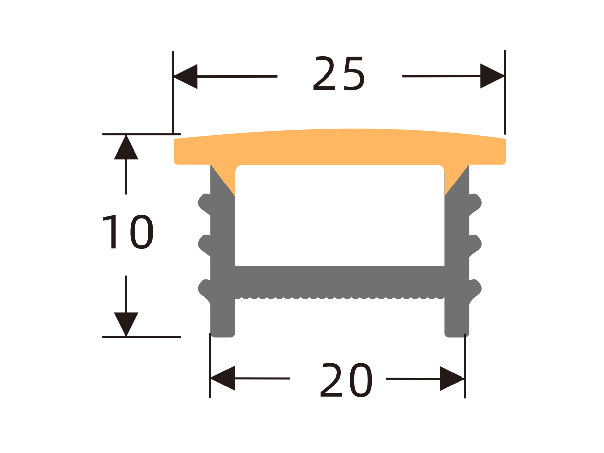
L2014
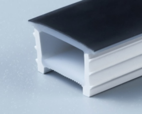
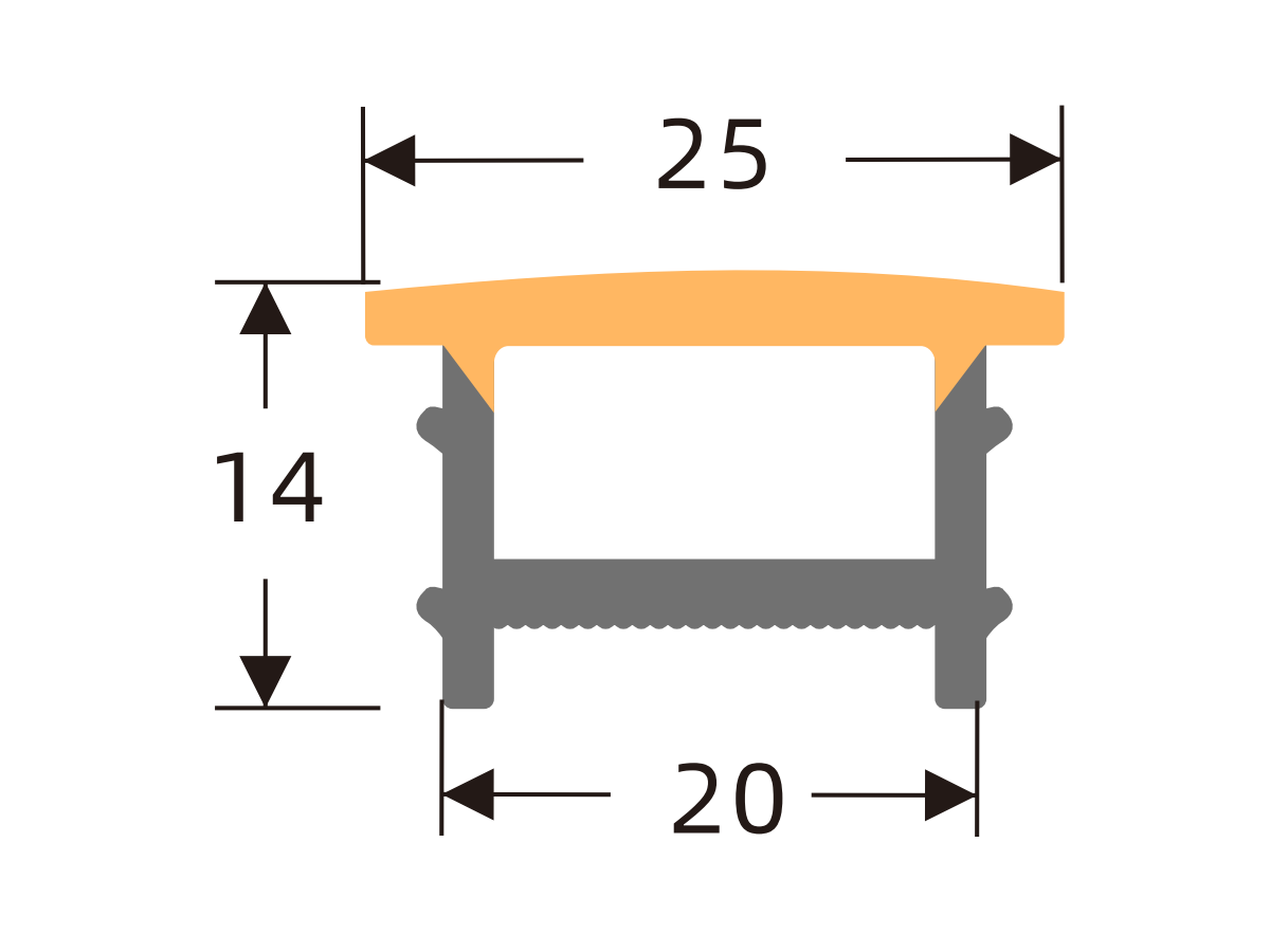
L2510
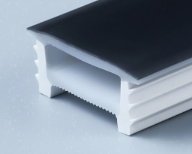
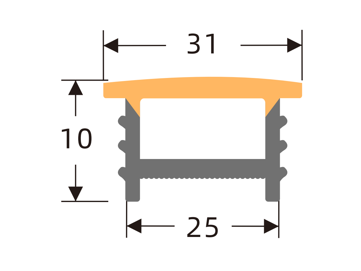
L2020
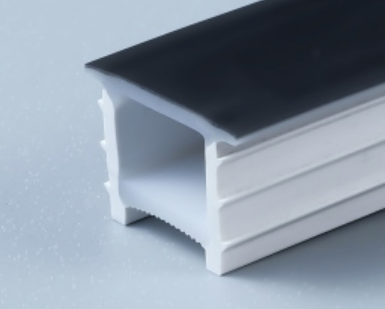
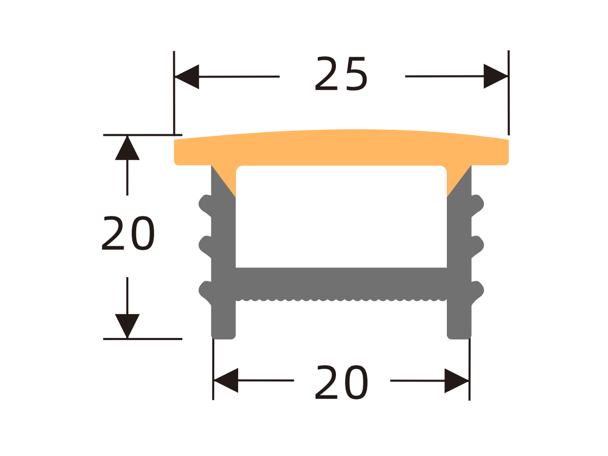
L2520
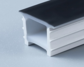
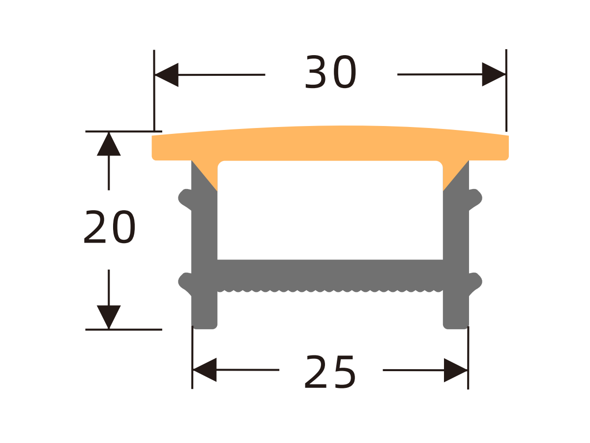
L3010
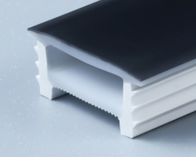
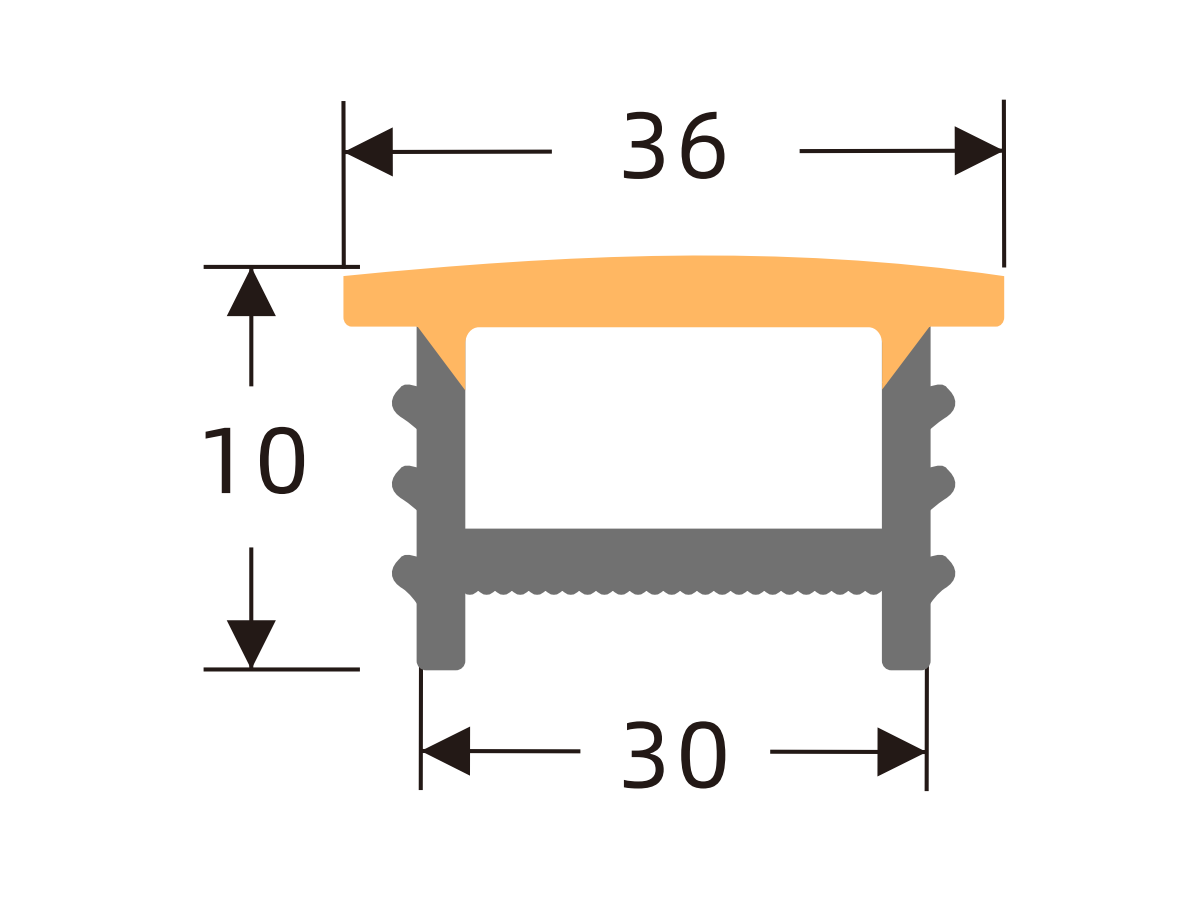
L3020
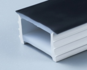
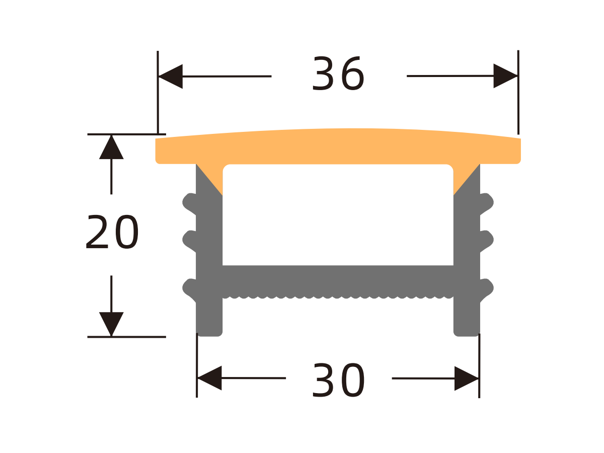
L4020
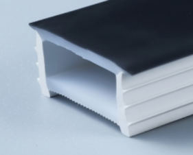
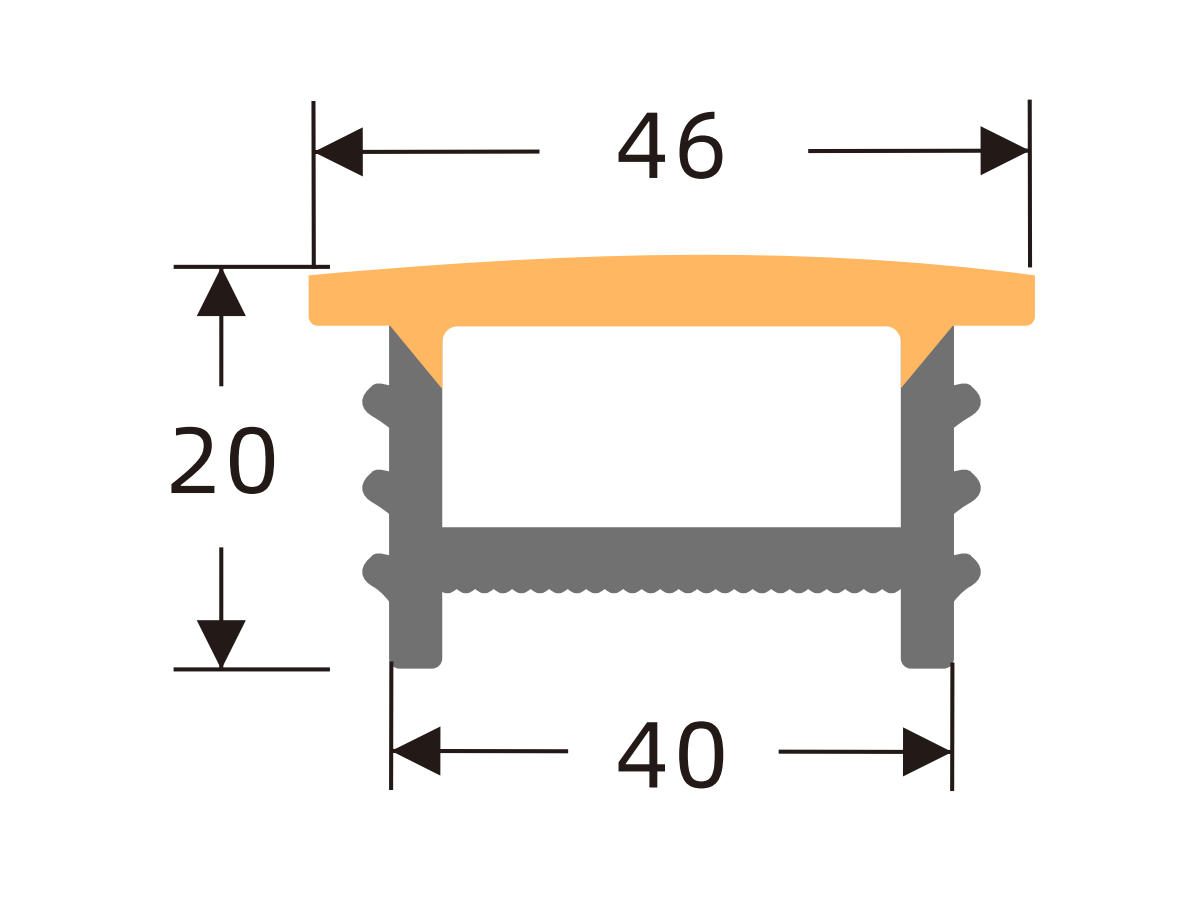
L4025
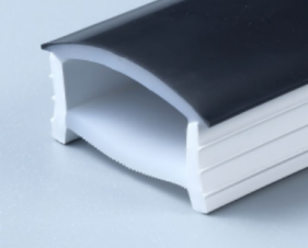
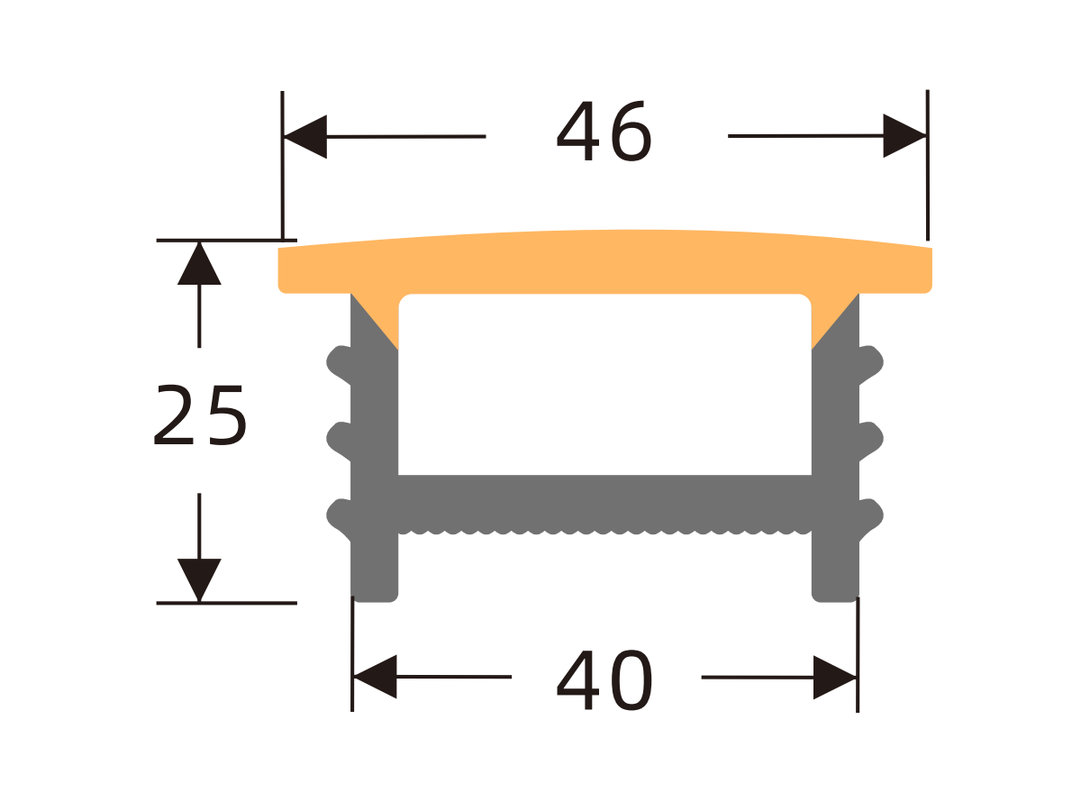
L5025
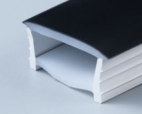
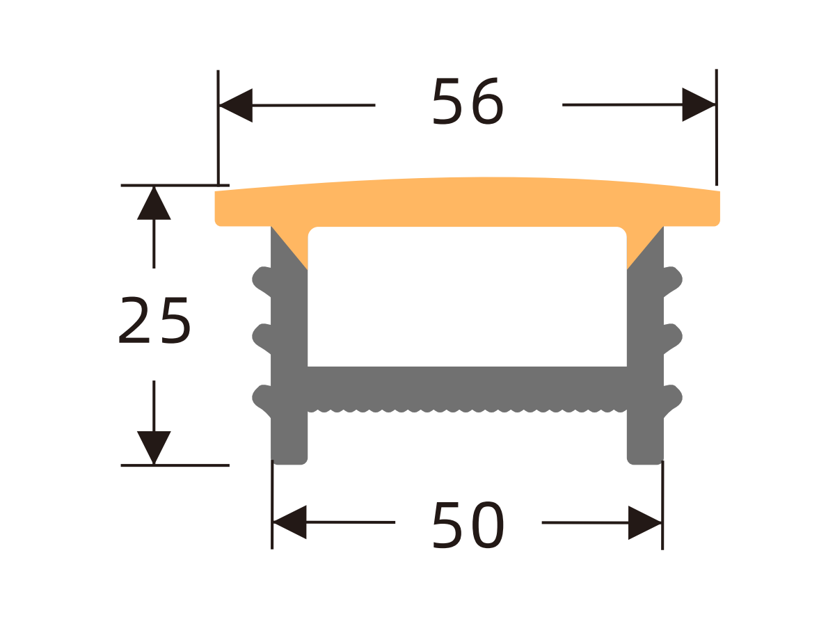
L1010
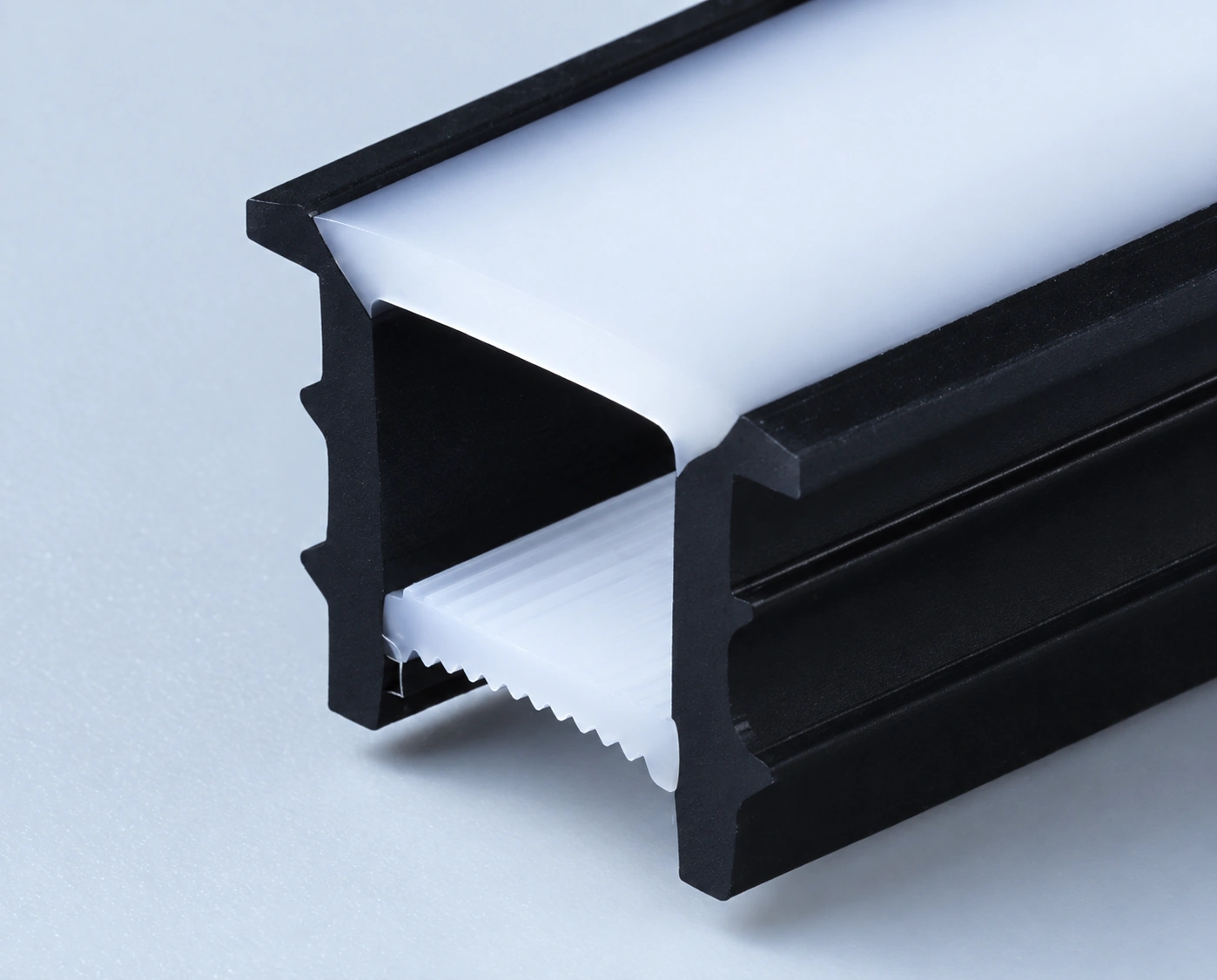
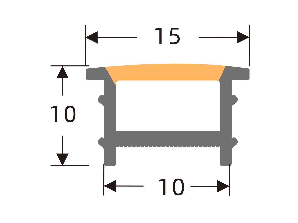
L1212
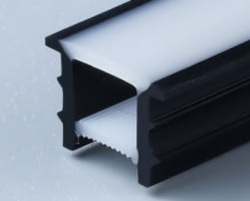
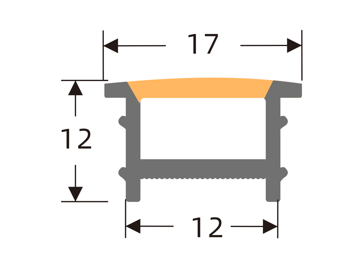
L1414
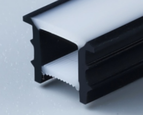
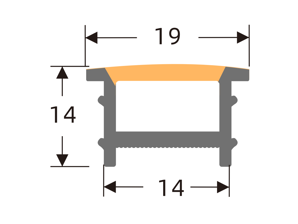
L1510
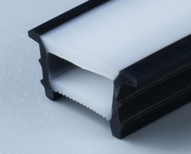
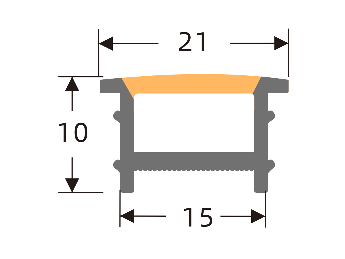
L1515
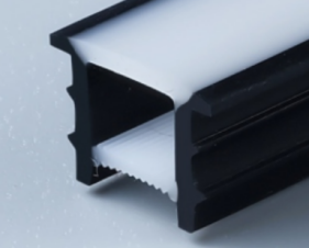
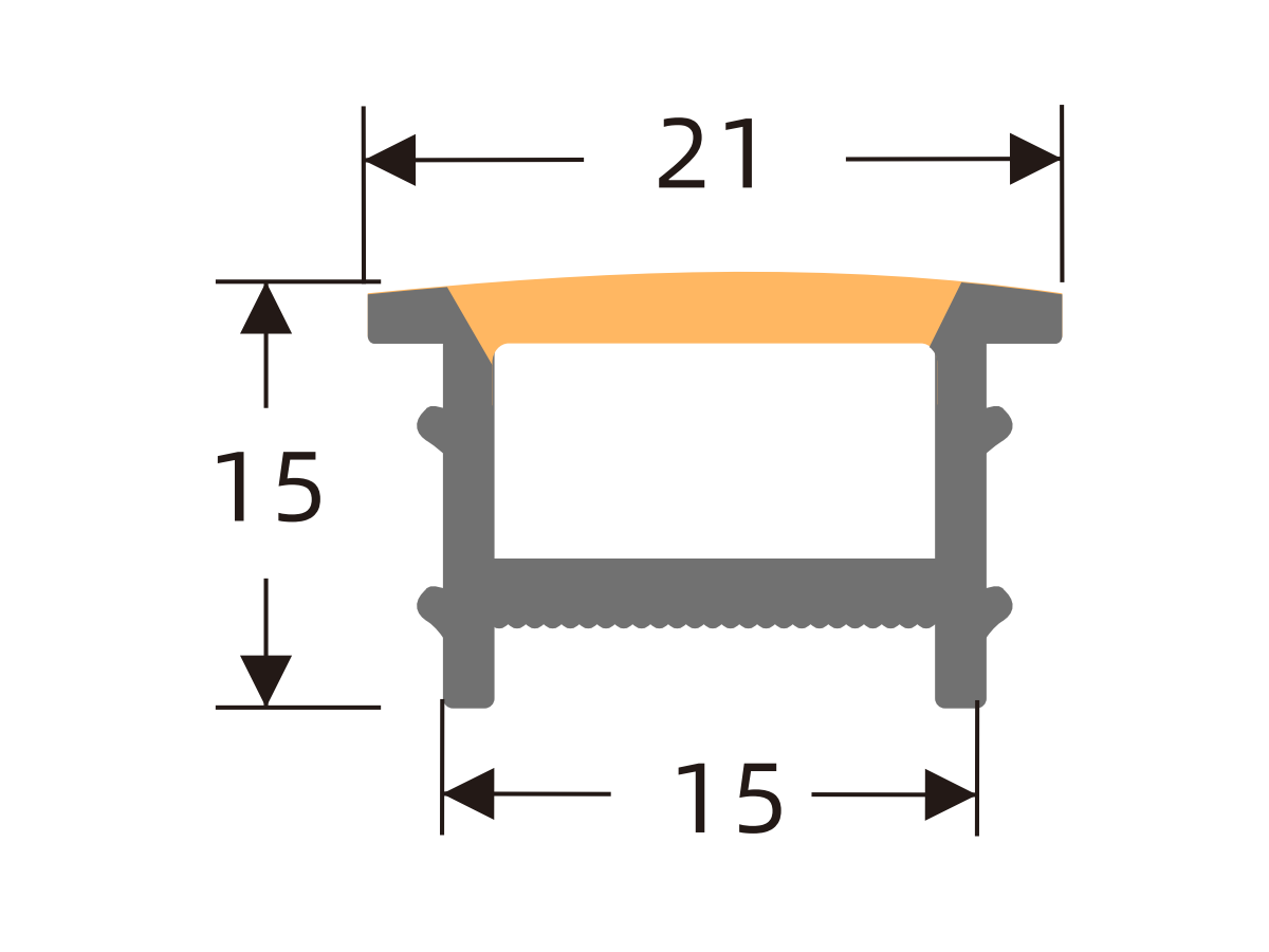
L1610
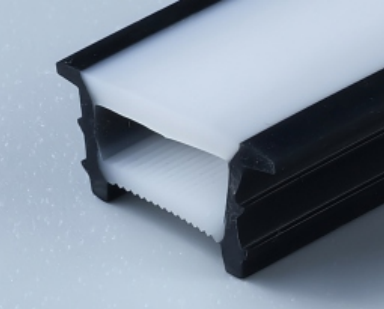
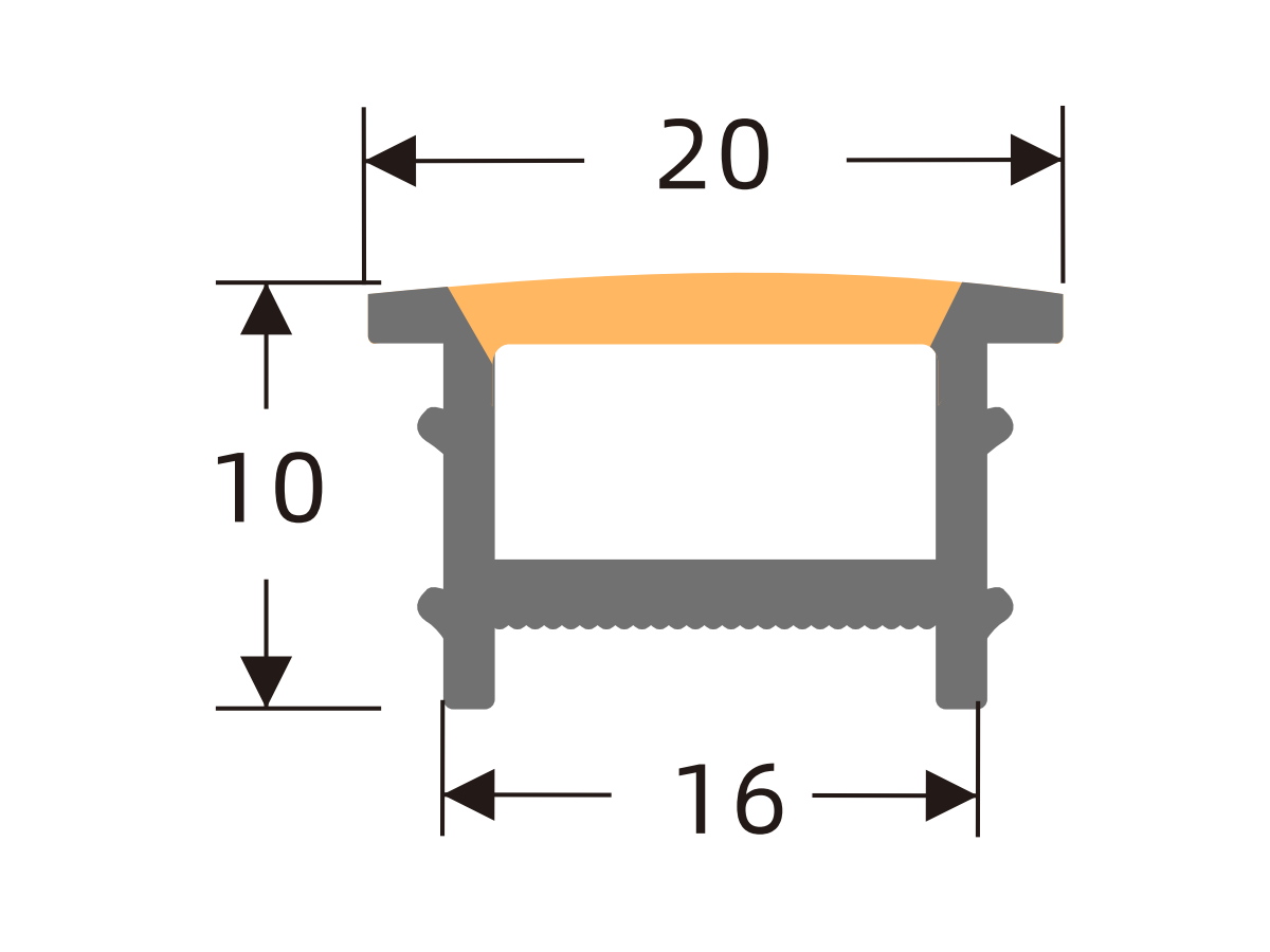
L1616
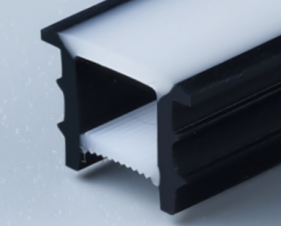
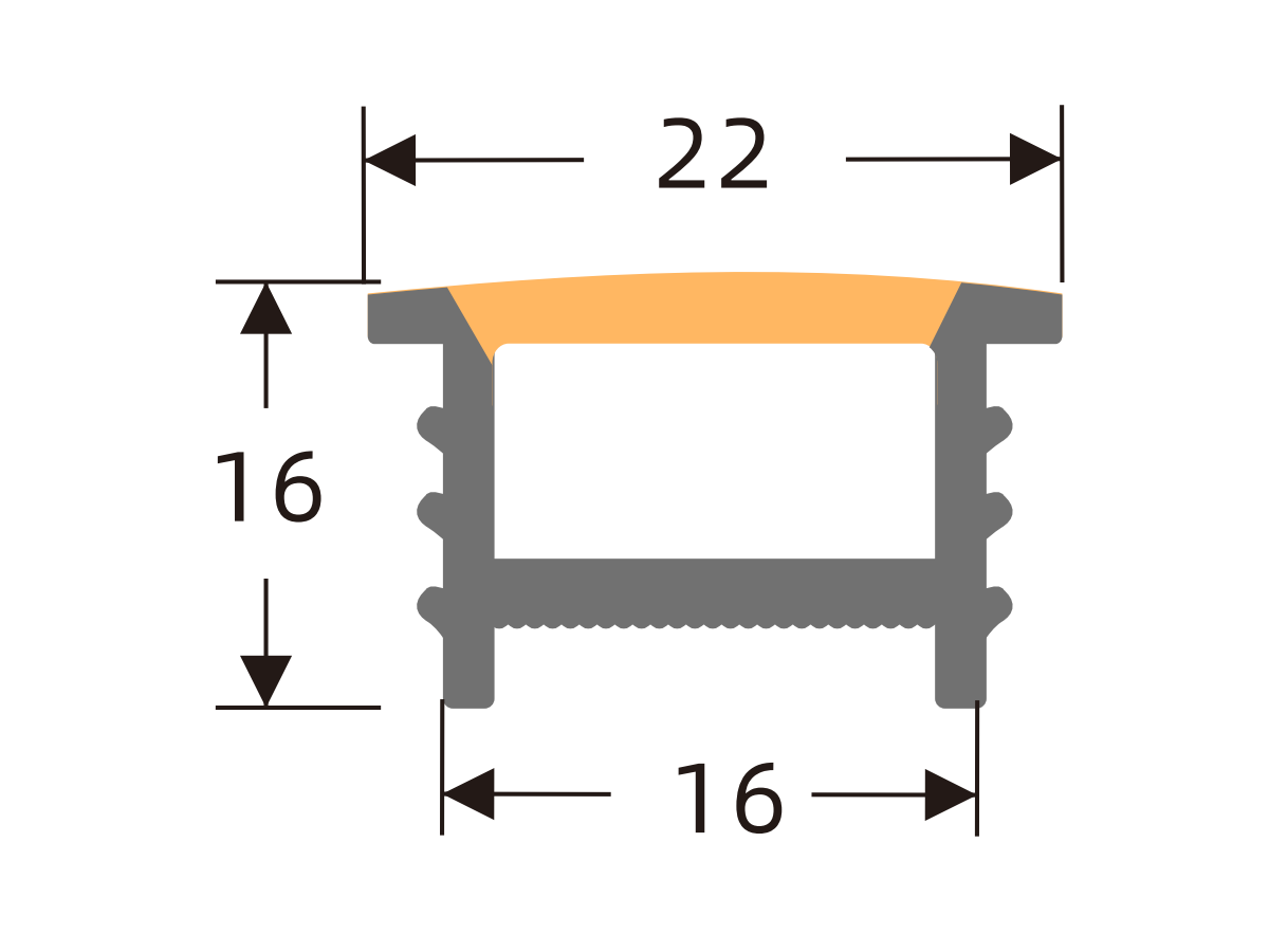
L2010
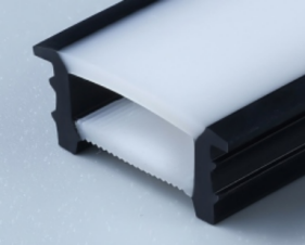
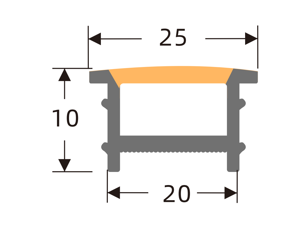
L2014
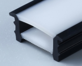
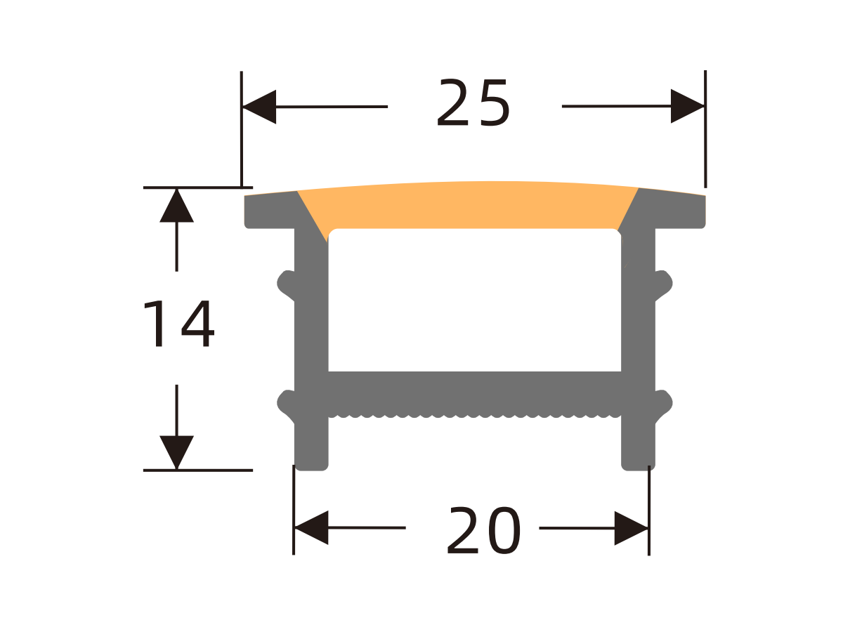
L2020
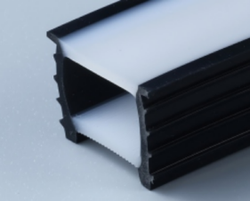
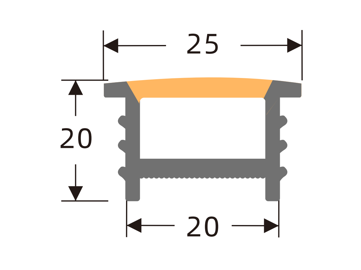
L2520
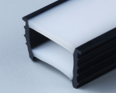
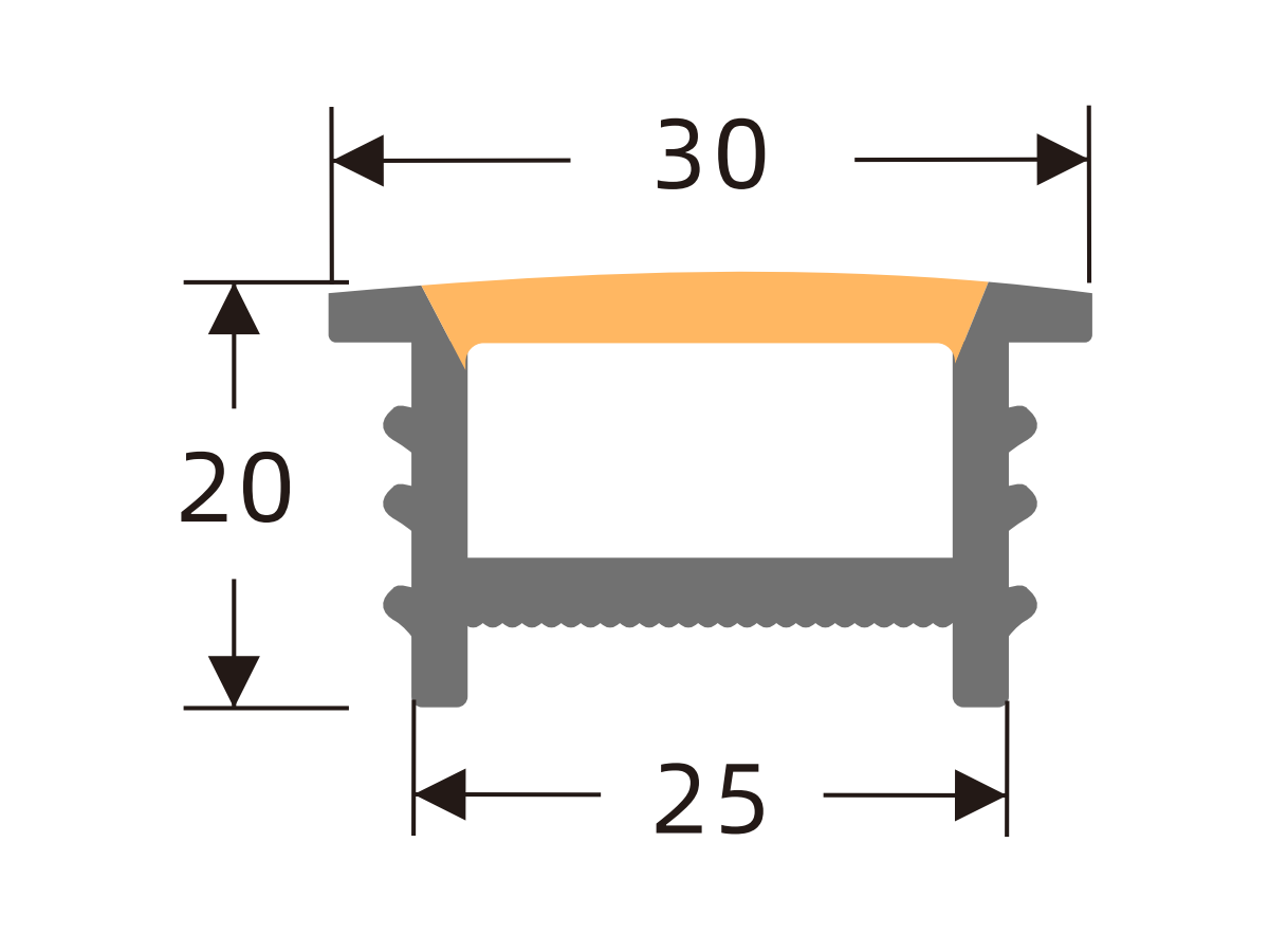
L3020